SC-F9200 Series Revision B
DISASSEMBLY & ASSEMBLY Disassembly and Assembly Procedure 134
SE Group Confidential (Related Staff Only)
3.4.4.7 Sub-M Board
1. Remove the Media Loading Lever. (p210)
2. Remove the Right Upper Cover. (p103)
3. Remove the Right Cover. (p108)
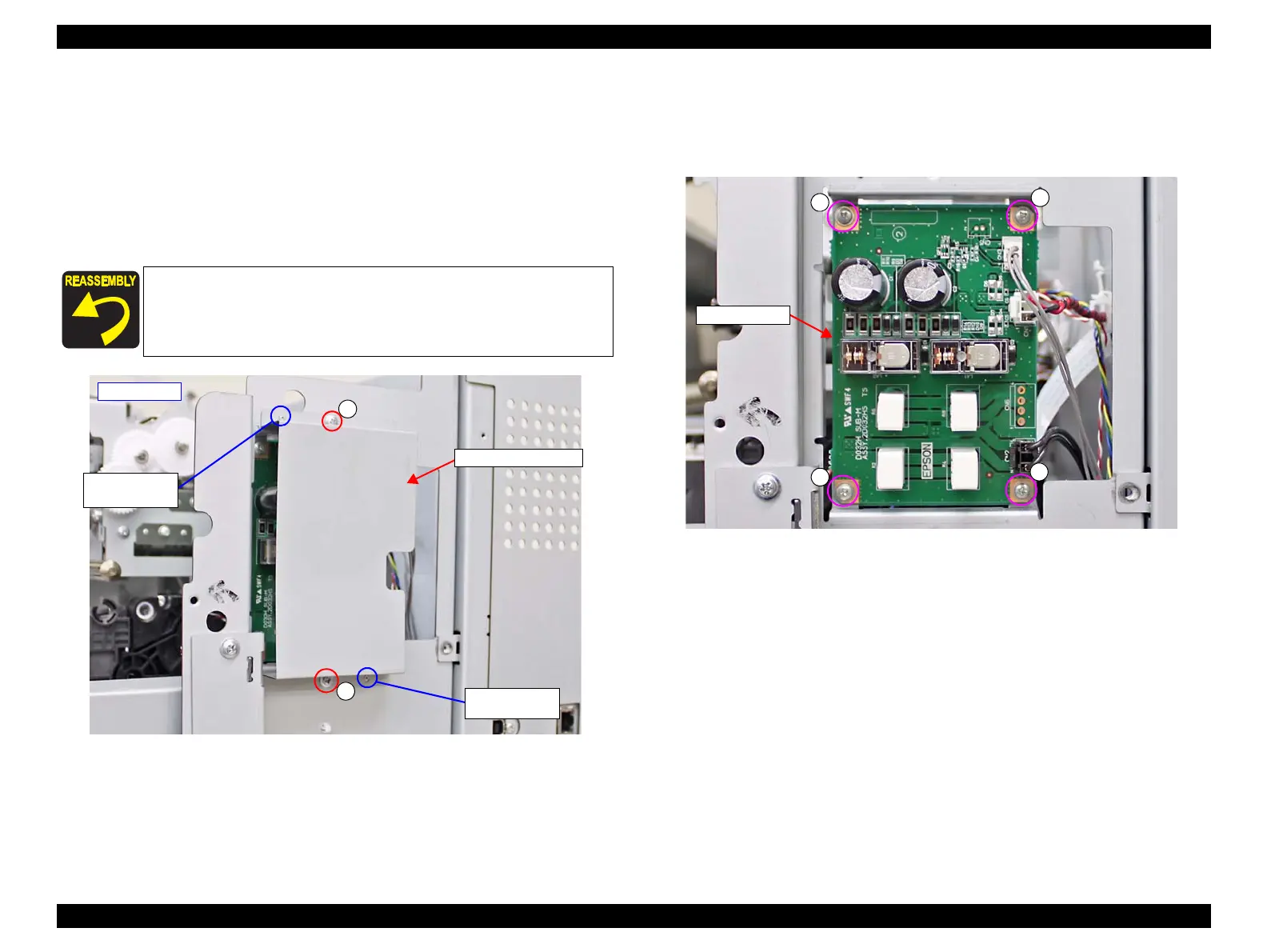
4. Remove the two screws, and remove the Sub-M Board Cover.
A) Silver M3x8: 2 pcs
Figure 3-65. Removing the Sub-M Board Cover
5. Disconnect all cables connected to the Sub-M Board.
6. Remove the four screws, and remove the Sub-M Board.
B) Silver M3x6 screw: 4 pcs
Figure 3-66. Removing the Sub-M Board
When installing the Sub-M Board Cover, insert the two dowels of
the frame into the two positioning holes on the Sub-M Board
Cover.
A
A
- Right side -
Positioning hole
and dowel
Sub-M Board Cover
Positioning hole
and dowel

 Loading...


