SC-F9200 Series Revision B
DISASSEMBLY & ASSEMBLY Disassembly and Assembly Procedure 178
SE Group Confidential (Related Staff Only)
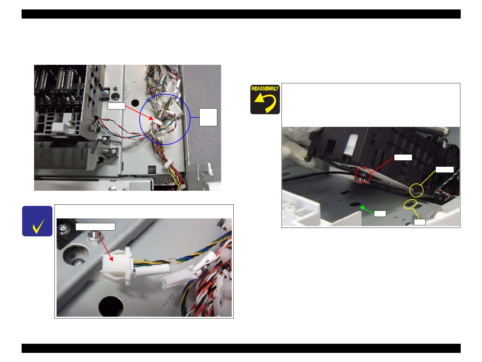
9. Open the clamp.
10. Disconnect the cable from the three relay connectors (No.36, No.37, and No.79)
and release the cables.
Figure 3-119. Removing the Relay connector
11. Remove the three screws that secure the Pump Cap Unit 2.
B) Silver M3x8 S-tite screw with captive washer: 3 pcs
12. Pull the Pump Cap Unit 2 frontward to disengage the hook, and remove the Pump
Cap Unit 2 in the right direction avoiding contact with the CR shaft or any other
parts.
Leave the relay connectors at the main body side to reuse them.
Install the Pump Cap Unit 2 while aligning its screw head with
the hole on the frame. If they do not match, the current
attachment position is wrong.
Align the hook on the Pump Cap Unit 2 with the hole on the
frame shown in the figure below.

 Loading...


