SC-F9200 Series Revision B
DISASSEMBLY & ASSEMBLY Disassembly and Assembly Procedure 222
SE Group Confidential (Related Staff Only)
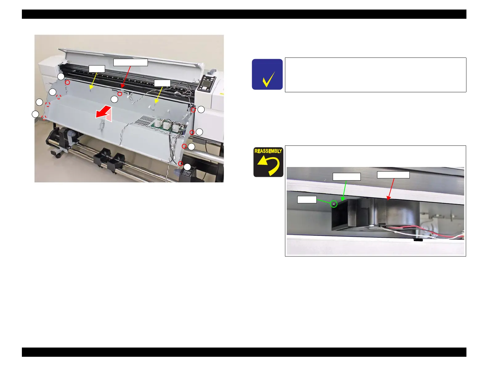
Figure 3-172. Removing the Front Frame
8. Disconnect the cable from the relay connector.
9. Release the cable from the clamp.
10. Pass the rolled A4 paper through the hole on the frame.
11. Insert the screwdriver through the rolled A4 paper to remove the two screws, and
remove the Suction Fan.
B) Silver M3x40 screw: 2 pcs
s
A
A
A
A
A
A
A
A
A
Front Frame
Hook
Hook
To prevent the screw of the Suction Fan from dropping inside the
frame, remove the screw with rolled A4 paper put through the hole
of the frame.
Install the Suction Fan with its duct part in contact with the dowel
of the frame.
Dowel
Suction Fan
Duct part

 Loading...


