SC-F9200 Series Revision B
DISASSEMBLY & ASSEMBLY Disassembly and Assembly Procedure 221
SE Group Confidential (Related Staff Only)
3.4.6.9 Suction Fan
1. Remove the After Heater. (p233)
2. Remove the Cooling Fan. (p235)
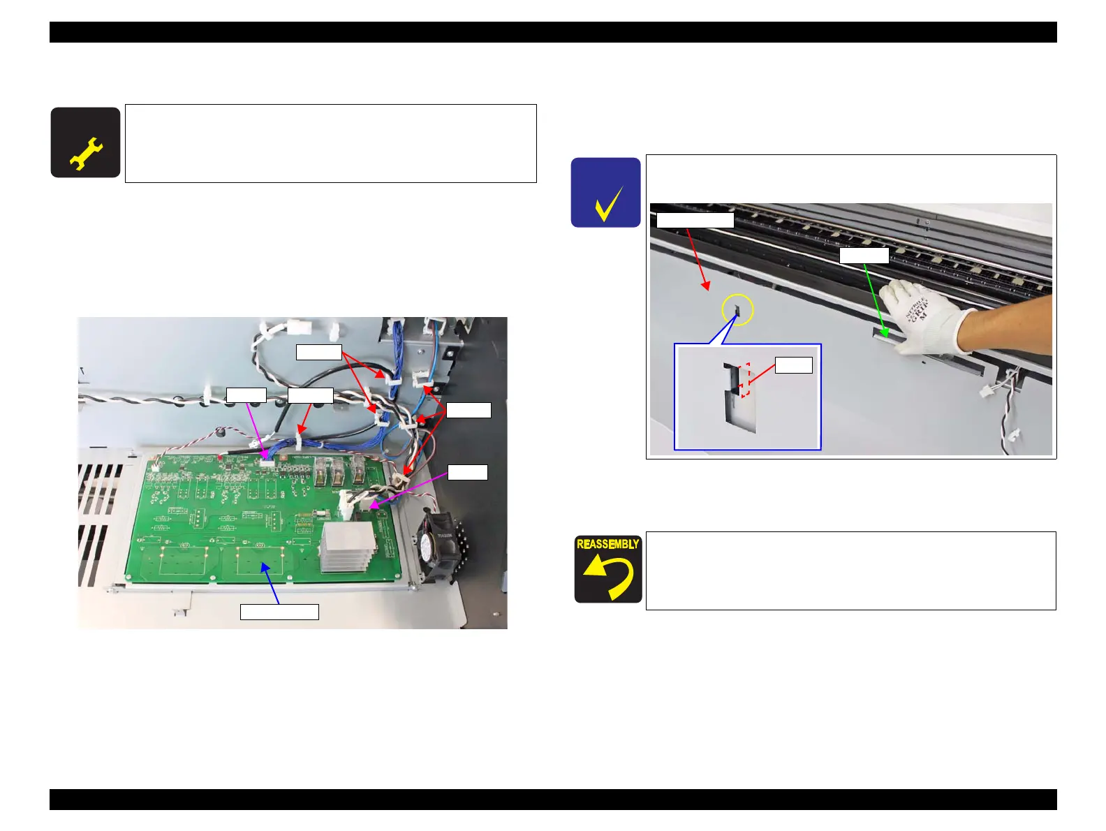
3. Release the cables from the six clamps.
4. Disconnect the cables from the connectors (CN500 and CN502) on the Sub-E
Board.
Figure 3-171. Releasing the Cables
5. Remove the nine screws that secure the Front Frame.
A) Silver M3x8 S-tite screw with built-in washer: 9 pcs
6. Lift the Front Frame to disengage the two ribs.
7. Taking care not to let the Front Frame get contact with the main body, remove the
Front Frame in the direction of the arrow.
A D J U S T M E N T
R E Q U I R E D
When replacing/removing this part, refer to “4.1.2 Adjustment
Items and the Order by Repaired Part” (p260) and make sure to
perform the specified operations including required adjustment.
CN502
CN500
Sub-E Board
Clamps
Clamp
Clamps
To disengage the hooks, lift the Front Frame holding the handle, or
lift it by raising the bottom of the frame.
When attaching the Front Frame, take extra care not to let the
cables get caught between the Front Frame and main body.

 Loading...


