SC-F9200 Series Revision B
DISASSEMBLY & ASSEMBLY Disassembly and Assembly Procedure 226
SE Group Confidential (Related Staff Only)
3. Remove the Driven Roller Gear from the Shaft.
B) Silver M3x8 pan head sems screw: 1 pcs
Install the Shaft in the following procedure.
1. Move the Media Loading Lever to the front side, and set it to
the Hold position.
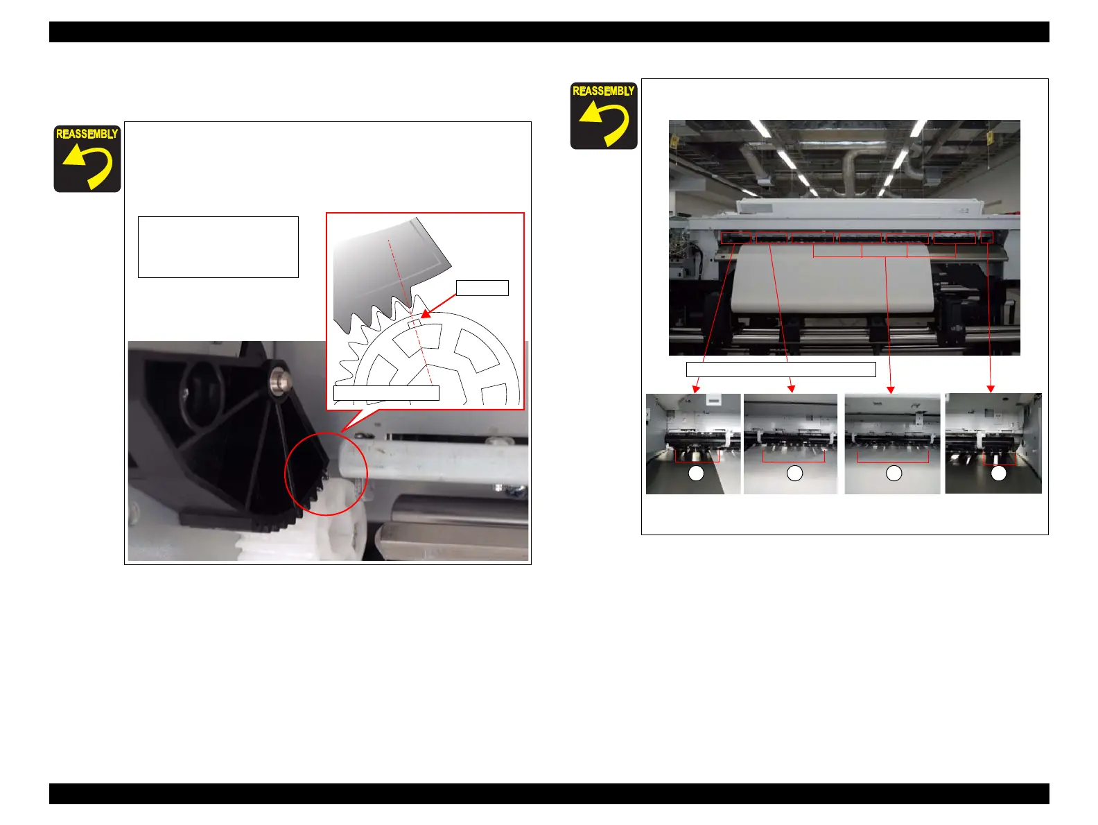
2. Install the Driven Roller Gear while aligning its phase
according to the figure below.
Driven Roller Gear
Concave
<Phase alignment>
Align the concave section of the
Driven Roller Gear with the first
tooth of the black gear.
3. Tighten the screw of Shaft to the figure below.
4. Check the release and hold to move Media Loading Lever after
tighten 6pcs screws.
2
The number of Driven Roller Holder
3 4 1

 Loading...


