SC-F9200 Series Revision B
DISASSEMBLY & ASSEMBLY Disassembly and Assembly Procedure 248
SE Group Confidential (Related Staff Only)
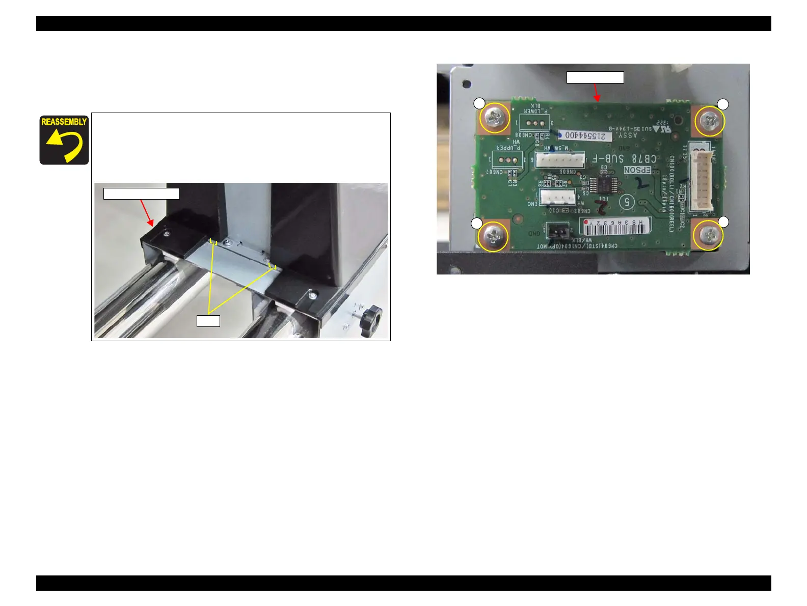
7. Disconnect all cables from the connectors on the Sub-F Board.
8. Remove the four screws, and remove the Sub-F Board.
C)Silver M3x8 S-tite screw: 4 pcs
Figure 3-204. Removing the Sub-F Board
When installing the Sub-F Board, make sure to attach it in the
correct orientation as shown in Figure3-204.
Insert the two tabs of the Right Reel Cover into the two
positioning holes on the frame.

 Loading...


