SC-F9200 Series Revision B
DISASSEMBLY & ASSEMBLY Disassembly and Assembly Procedure 247
SE Group Confidential (Related Staff Only)
3.4.9.4 Sub-F Board (Reel)
1. Remove the Roll Paper Holder of the Right Reel Unit. (p246)
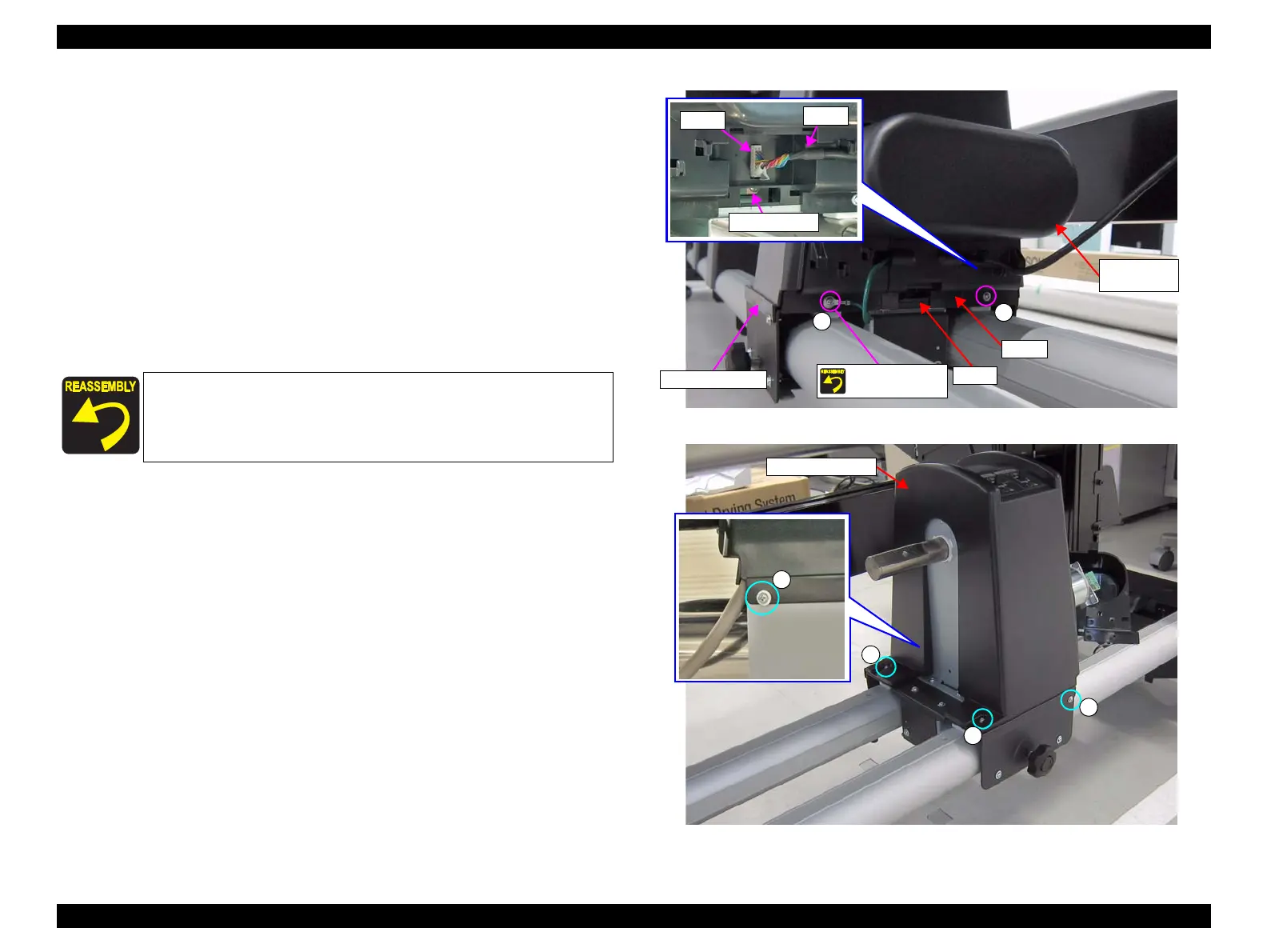
2. Disengage the hook, and remove the cover.
3. Disconnect the cable from the connector (CN600) on the Sub-F Board.
4. Remove the four screws. (
See Figure 3-203.)
A) Silver M3x8 S-tite screw with built-in washer: 4 pcs
5. Remove the two screws that secure the Right Reel Side Cover. (See Figure
3-202.)
B) Silver M3x8 S-tite screw with built-in washer: 2 pcs
6. Slightly lift the Right Reel Cover, and remove the Right Reel Side Cover.
Figure 3-202. Removing the Cover
Figure 3-203. Removing the Right Reel Side Cover
Tighten the screw that secures the Right Reel Side Cover together
with the grounding wire.
B
B
Right Reel
Side Cover
Right Reel Unit
Secure with the
grounding wire.
Hook
Cover

 Loading...


