Appendix
Rev. A
A-
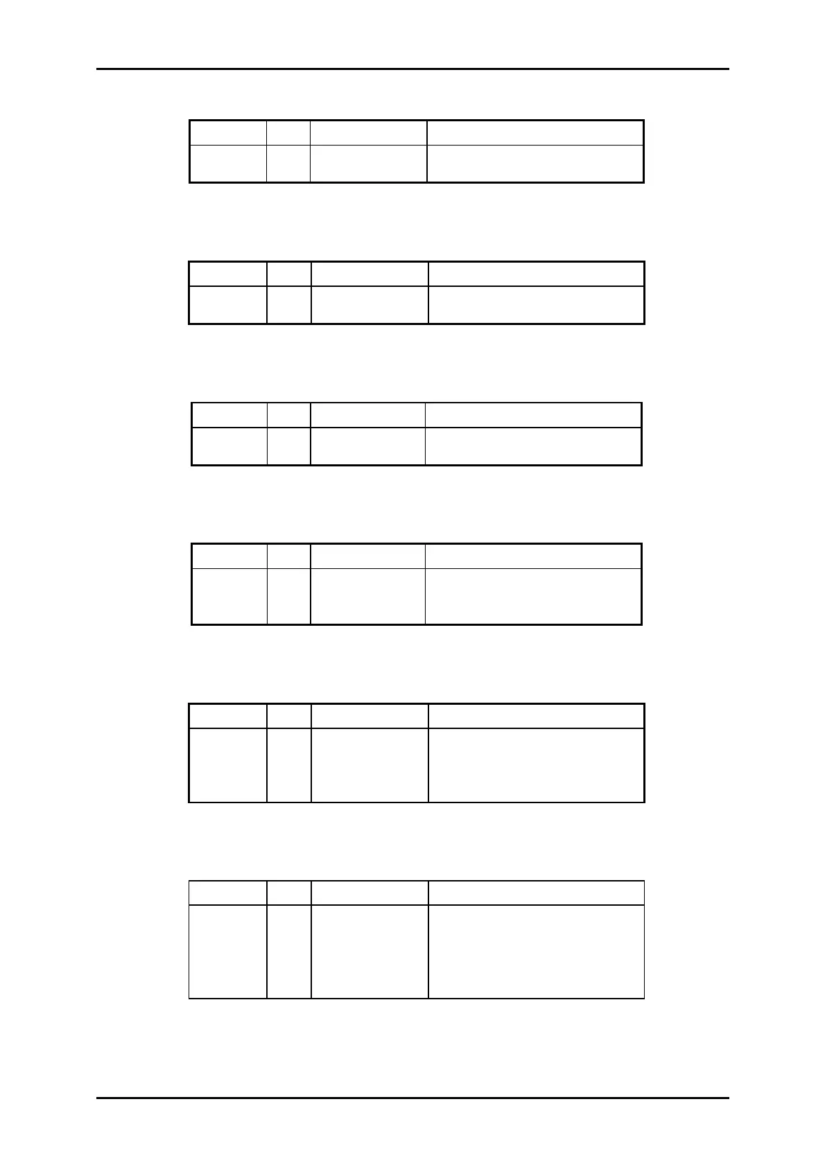
Pin No. I/O Signal Name Description
1 I REL Release sensor signal
2
GND Ground
Pin No. I/O Signal Name Description
1 I PE_F Front PE sensor signal
2
GND Ground
Pin No. I/O Signal Name Description
1 I PE_R Rear PE sensor signal
2
GND Ground
Pin No. I/O Signal Name Description
1 I HP HP sensor signal
2
+ 5 + 5 VDC
3
GND Ground
Pin No. I/O Signal Name Description
1 I IC_M0 Ink cartridge sensor signal
2
GND Ground
3 I IC_M1 Ink end sensor signal
4
GND Ground
Pin No. I/O Signal Name Description
1
NC
2 I ASF_PW ASF PW sensor signal
3
+ 5 + 5 VDC
4
GND Ground
5
NC
Table A-2. Connector Pin Assignment (CN3)
Table A-3. Connector Pin Assignment (CN4)
Table A-4. Connector Pin Assignment (CN5)
Table A-5. Connector Pin Assignment (CN6)
Table A-6. Connector Pin Assignment (CN7)
Table A-7. Connector Pin Assignment (CN8)

 Loading...


