EPSON Stylus COLOR 3000
Rev. A
3-3
3.2.11.15 LD Shaft Removal
1. Remove the printer mechanism unit. (See Section 3.2.6.)
2. Remove the paper eject frame unit. (See Section 3.2.11.6.)
3. Remove the CR unit. (See Section 3.2.11.14.)
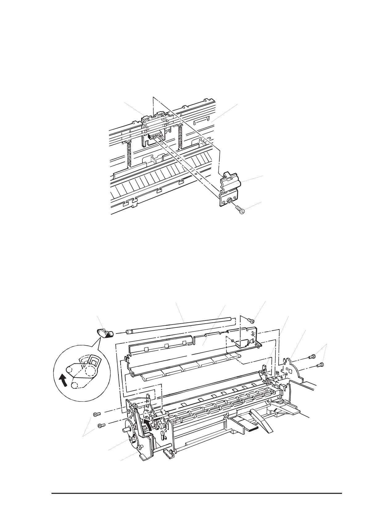
4. Remove 1 screw (CBP, 3x8) securing the ink supplying tube unit to the tube fixing holder on the printer
mechanism with the tube fixing holder (B). Then release the tubes from printer mechanism.
5. Set the release lever to the tractor side and push the release transmission lever* inward. Then turn the
sub tractor release cam as shown in Figure 3-30 until it fits into the cutout on the left frame unit .Then
release the joint for the sub tractor cam and left frame unit.
* Release transmission lever: A black plastic lever located at the inner side of the left frame
6. Pull out the tractor release shaft along with the tractor sub release cam.
7. Remove 5 screws (CBS, 3X6) securing the base frame assembly to the printer mechanism unit. Then
remove the base frame assembly.
Tube Fixing Holder
Base Frame Unit
Tube Fixing Holder ;B
CBP Screw (3x8)
Figure 3-29. Ink Tube Unit Removal
Sub Tractor Release Cam
Tractor Release Shaft
Base Frame Unit
CBS Screw (3X6)
Middle Frame Unit
Right Main Frame
CBS Screws (3X6)
CBS Screws
(3X6)
Left Frame Unit
Release Lever
Figure 3-30. Base Frame Assembly Removal