Disassembly and Assembly
Rev. A
3-1
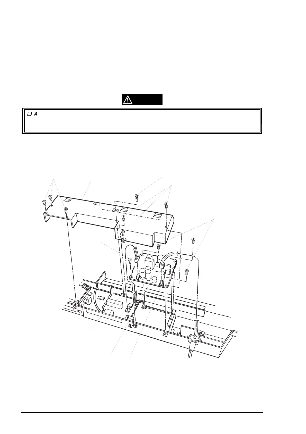
3.2.7 PSB/PSE Board Assembly Removal
1. Remove the upper housing. (See Section 3.2.1.)
2. Remove the printer mechanism unit. (See Section 3.2.6.)
3. Remove 7 screws (6 CBS screws , 3X8 and 1 CBP screw, 3X12) securing the upper shield plate to the
lower housing.
4. Disconnect the power cable and connector cable for the main board assembly from the CN1 and CN2,
respectively.
5. Remove 4 screws (CBS, 3X6) securing the PSB/PSE board assembly to the lower housing, then
remove the PSB/PSE board.
WARNING
After disconnecting the power cable from the AC socket, never disconnect the cable from
the CN1 for about 5 minutes, since the capacitor on the C172 PSB/PSE board is still
discharging electricity.
CBS Screws (3X6)
Upper Shield Plate
CBP Screw (3X12)
CN2
PSB/PSE Board Assembly
CN1
CBS Screws (3X6)
CBS Screws (3X6)
CBS Screw (3X6)
Figure 3-9. PSB/PSE Board Removal