Disassembly and Assembly
Rev. A
3-2
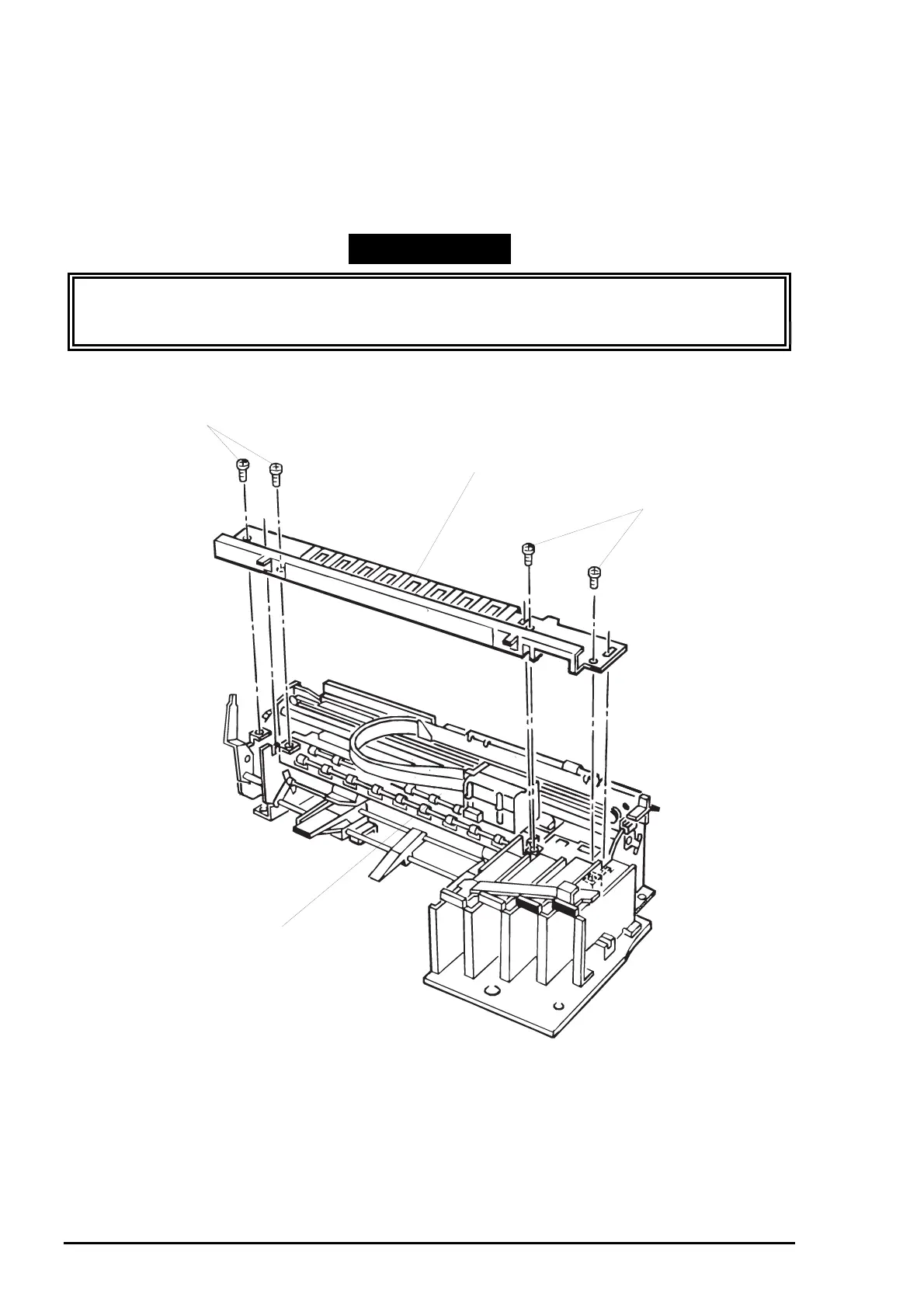
3.2.11.6 Paper Eject Frame Unit Removal
1. Remove the printer mechanism unit. (See Section 3.2.6.)
2. Remove connector cables for the HP sensor and cover open sensor from the connectors on the
sensors.
3. Remove 4 screws (CBS, 3X6) securing the paper eject frame unit to the printer mechanism unit.
4. Remove the paper eject frame unit from the printer mechanism unit by releasing the joint with the CR
unit.
WORK POINT
When removing the paper eject frame unit, insert a piece of clean paper or equivalent
between the platen surface in the paper eject frame unit and printheads in the CR unit to
protect the printheads.
CBS Screws (3X6)
Printer Mechanism Unit
CBS Screws (3X6)
Paper Ejecft Frame Unit
Figure 3-19. Paper Eject Frame Unit