EPSON Stylus COLOR 3000
Rev. A
3-2
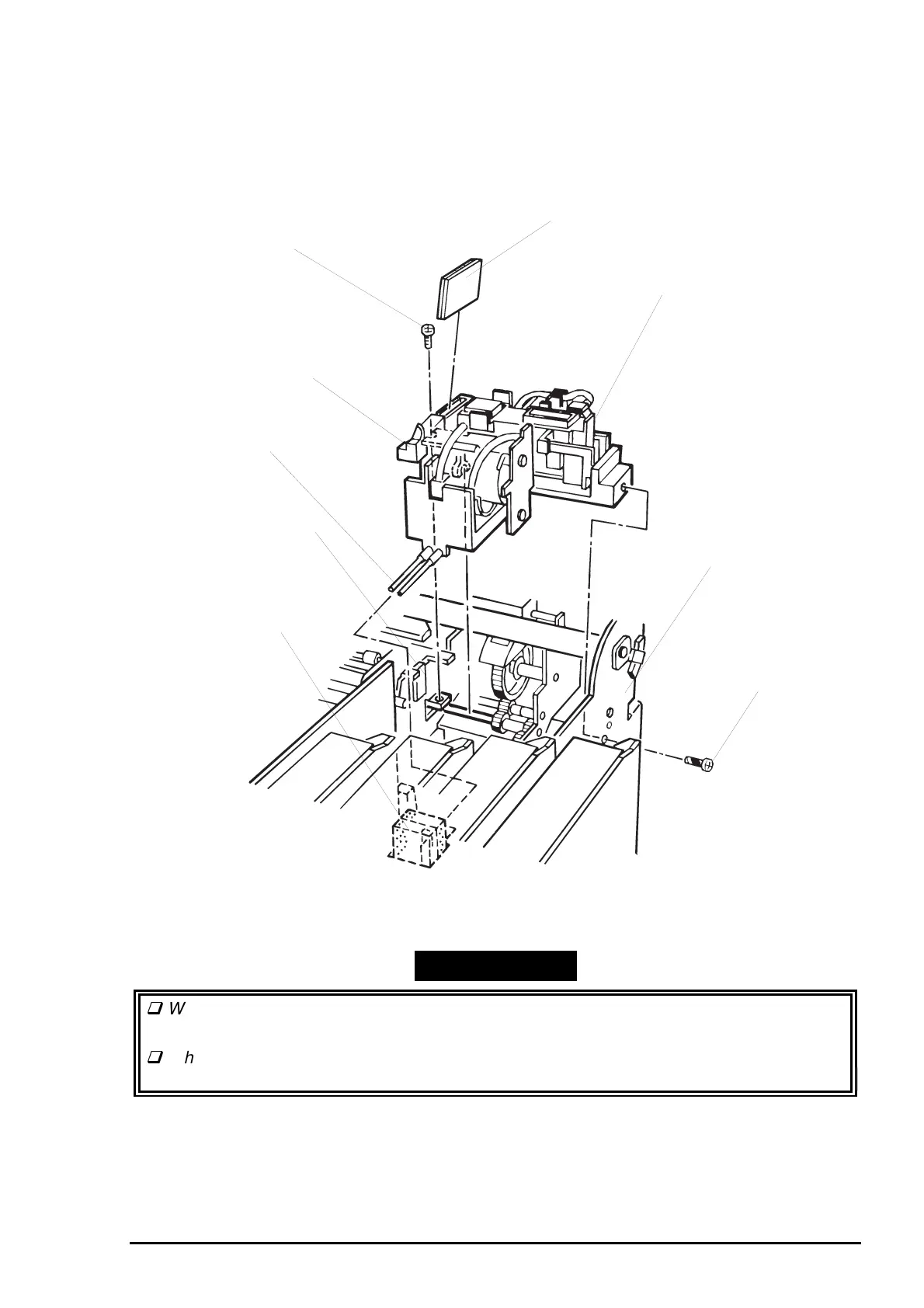
3.2.11.7 Pump Unit Removal
1. Remove the printer mechanism unit. (See Section 3.2.6.)
2. Remove the paper eject frame unit. (See Section 3.2.11.6.)
3. Remove 2 screws (1 CBS, 3X6 and 1 CBP, 3X8) securing the pump unit to the printer mechanism unit.
Then remove the pump unit.
WORK POINT
When installing the head cleaner to the pump unit, face the rubber part of the clear to the
pump side, as shown in Figure 3-20.
When installing the pump unit, place the tubes into the cutout first and then insert the sub
waste ink pads to set the tubes between them.
CBS Screws (3X6)
Head Cleaner
Draining Pipe
ASF Transmission Frame Unit
Sub Waste Ink Drain Pad
CBP Screw (3X8)
Right Main Frame
Pump Unit
Head Cleaner Lever
(See Secction 3.2.11.14, Step 6.)
Figure 3-20. Pump Unit Installation