Disassembly and Assembly
Rev. A
3-2
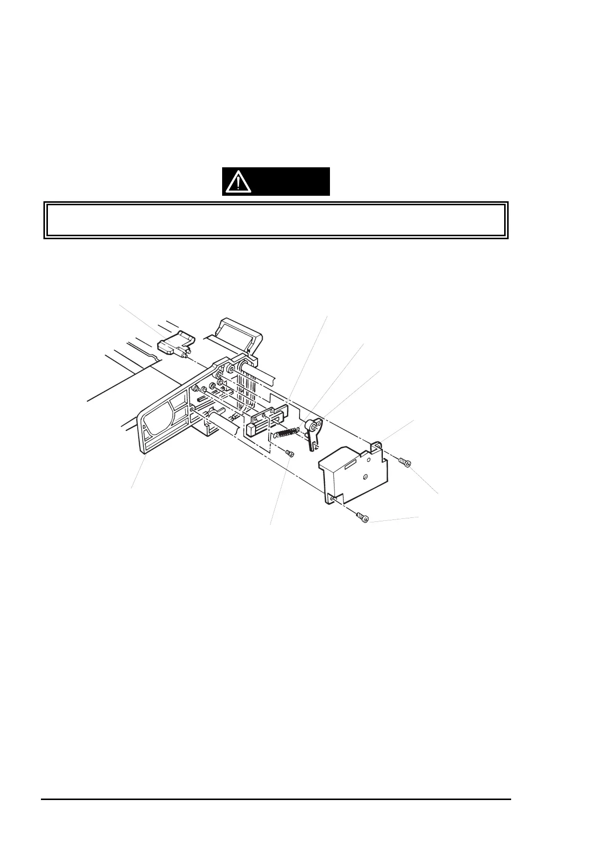
3.2.11.9 PQ (Paper Quantity) Sensor Board Assembly Removal
1. Remove the printer mechanism unit. (See Section 3.2.6.)
2. Remove the edge guide unit. (See Section 3.2.11.8.)
3. Remove 2 pan camera screws (2X5.5) securing the PQ sensor cover to the edge guide unit.
4. Remove 1 tension spring securing the PQ sensor sub lever to the PQ sensor, and remove the PQ
sensor sub lever.
5. Remove 1 pan camera 1B tight screw (2X3.5) securing the PQ sensor to the right edge guide. Then
remove the PQ sensor board assembly.
Do not apply too much torque when tightening the screws. Otherwise, the threads of the
tapped holes in the edge guide unit might crush.
CAUTION
PQ Sensor Lever Assembly
Right Edge Guide
PQ Sensor Board Assembly
Tension Spring (0.84)
PQ Sensor Sub Lever
PQ Sensor Cover
Pan Camera 1B Tight Screw (2X3.5)
Pan Camera Screw
1 (2X5.5)
Figure 3-23. PQ Sensor Removal