Disassembly and Assembly
Rev. A
3-3
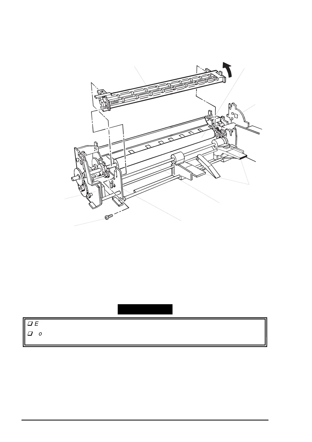
8. Remove 1 screw (CBP, 3X8) securing the paper eject drive unit to the left main frame assembly.
9. Attach the knob to the PF roller shaft. Then hold down the trigger lever on the right end of the PF roller,
and turn the PF roller shaft until the edge guides don’t lift up any further.
10. Remove the paper eject drive unit by lifting up the front part of the unit.
11. Remove the edge guide. (See 3.2.11.8.)
12. Remove 1 E-ring at the left end of the LD shaft.
13. Release the LD shaft bushing fixing the LD shaft to the left main frame assembly.
14. Release the joint for the LD gear on the right end of the LD shaft and ASF transmission gear in the
middle frame unit. Then shift the LD shaft toward the left frame assembly and remove it
-
WORK POINT
Engage the LD gear and the gear (29) in the ASF gear set as shown in Figure 3-32.
Don’t touch the gear surface with your bare hands, since damage on the gear causes
decline in paper feed accuracy.
Paper Eject Drive Unit
Left Main Frame Assembly
CBP Scerw (3X8)
Trigger Lever
PF Roller
LD shaft
Left Frame
Edge Guides
Figure 3-31. Paper Eject Drive Unit Removal