EPSON Stylus COLOR 3000
Rev. A
2-1
2.3.2
MAIN Control Board
This printer uses
MAIN for the main control circuit board. It consists of the following:
16-bit
H8S/2655 (IC5) Runs at 19.66 MHz
2 gate arrays E05B33 (IC6) Manages interfaces, motors and printheads.
E05B45 (IC16)
P-ROM, DRAM and MROM
Drivers Produces common voltage for printheads
Drives motors.
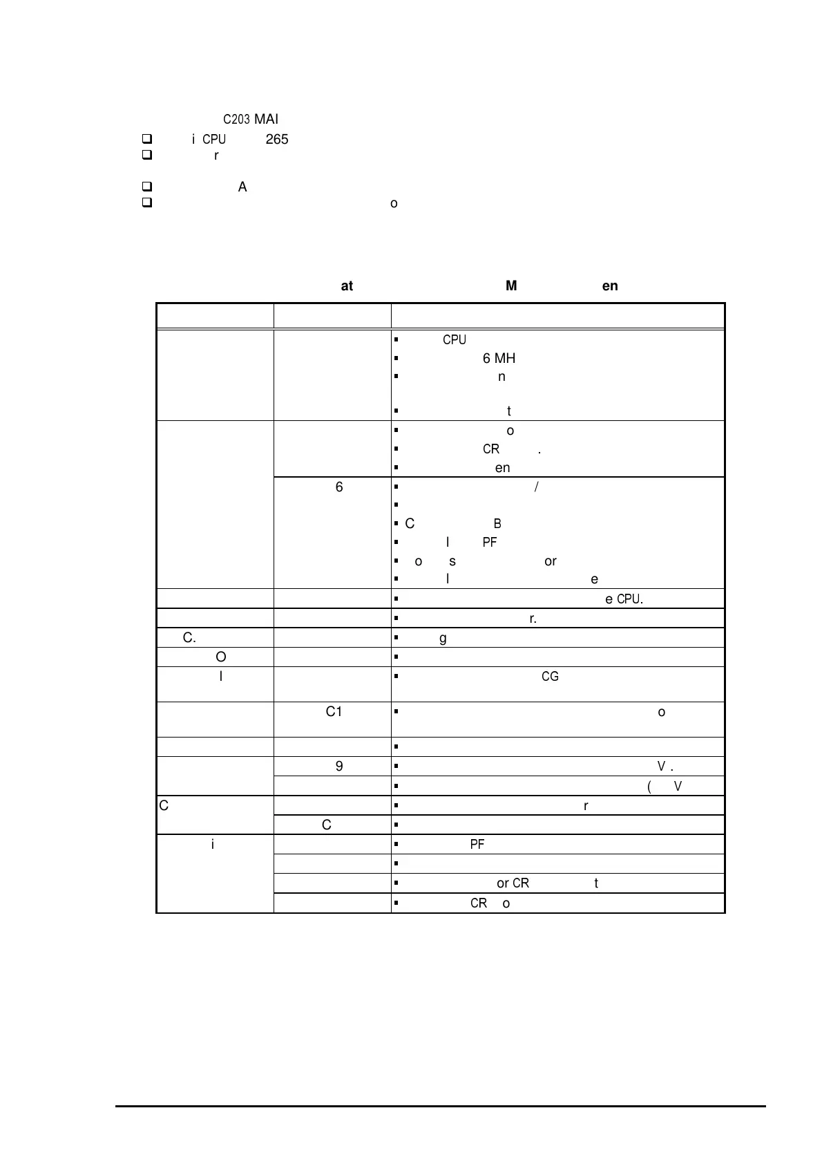
Table 2-8 and Figure 2-15 show the allocated functions for major components and the main control circuit
block diagram, respectively.
IC Location Function
CPU IC5
16-bit
Runs at 19.66 MHz
Controls the printer at the gate arrays IC5 and IC6
according to the program in P-ROM.
Monitors the printhead temperature.
Gate Array IC16
Controls the I/F for the control panel.
Controls the
motor.
Manages the sensors.
IC6
Controls the parallel I/F.
Controls the serial I/F.
Controls Type-
$
I/F.
Controls the
motor.
Controls the pump motor.
Controls black and color printheads.
DRAM IC12
Manages buffers, work area in the
%
SRAM IC14, IC28
Manages input buffer.
C.G. ROM IC11
Manages C.G. (Character Generator).
P-ROM IC13
Manages printer control program.
Optional ROM
IC7, IC10
For optional fonts and
(not attached as a
standard item.)
EEPROM IC1
Stores values for the default settings and other
values.
Timer counter IC IC2
Manages timers for the ink system.
Reset IC IC9
Outputs a reset signal to the logic line (+5
).
IC3
Outputs a reset signal to the power line (+42
).
Common driver IC IC22
Produces common voltage for the black printhead.
IC23
Produces common voltage for the color printhead.
Driver IC17
Drives the
motor.
IC18
Drives the pump motor.
IC25
D/A converter for
motor control
IC19, IC20
Drives the
motor.
Table 2-8. Location and function of the Major Components
 Loading...


