EPSON Stylus CX3100/3200 Revision A
Disassembly and Assembly Disassembly of Printer 47
6. Remove the Print Head.
7. Disconnect the Head FFC from the connector of the Print Head.
A D J U S T M E N T
R E Q U I R E D
Once you have replaced the Print Head with a new one, make the
following adjustments:
(Refer to “Adjustment by Adjustment Program” on page 59)
Head ID Input
Ink Charge
Bi-D Adjustment
Top Margin Adjustment
First Dot Position Adjustment
When you have removed once and then installed the Print Head,
make the following adjustments:
Head Cleaning
Bi-D Adjustment
Top Margin Adjustment
First Dot Position Adjustment
C H E C K
P O I N T
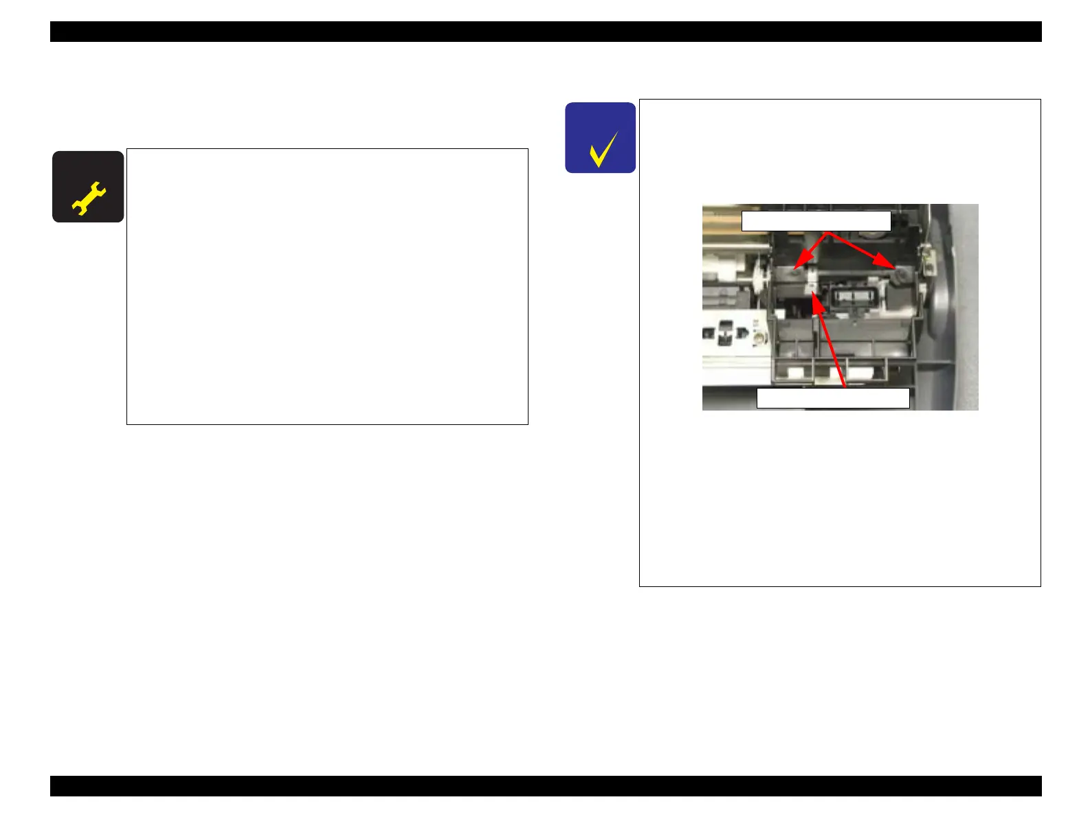
Installing the Print Head
1. Set the Head FFC in the holding portion (at C) of the Carriage
Unit. (See Figure 4-20, "Removing the FFC Holder", p. 46)
2. Make sure that the head grounding plate is installed on the
Carriage Unit properly.
Figure 4-22. Head Mounting Position
3. Install the Print Head so that the two holes are put properly on
the respective pins of the Carriage Unit. (See Figure 4-22,
"Head Mounting Position", p. 47)
4. Secure the Print Head with the one screw (C.B.P-Tite SCREW
3x8 F/Zn) and one screw (C.B.B.-Tite W2 2.5x5 F/Zb).
Screw tightening torque;
C.B.P-Tite 3x8 F/Zn:0.5-0.7Nm
C.B.B-Tite W2 2.5x5 F/Zb:0.15-0.25Nm
Head positioning pin
Head grounding plate
 Loading...