EPSON Stylus CX3500/CX3600/CX3650/CX4500/CX4600 Revision A
DISASSEMBLY AND ASSEMBLY Disassembly 121
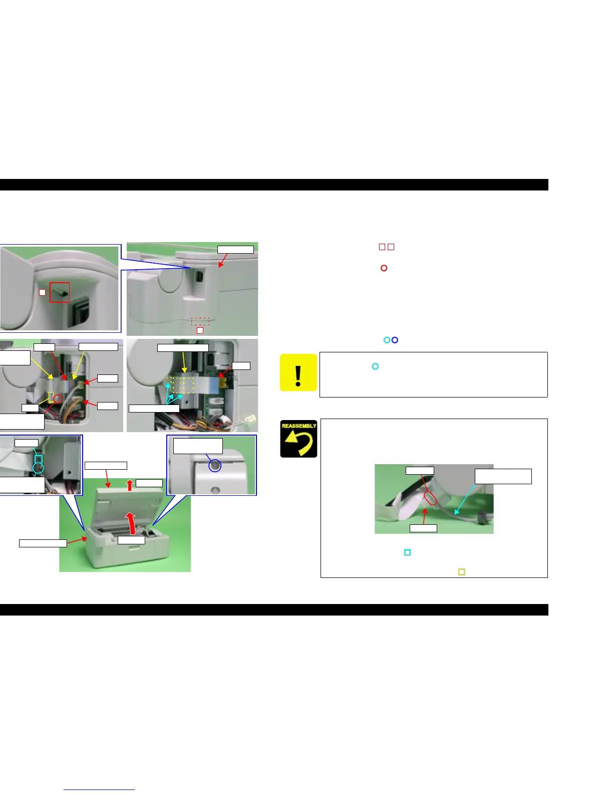
4.3.4 Scanner Unit
V External View (1)
Figure 4-5. Scanner Unit Removal
V Part/Unit that should be removed before removing Scanner Unit.
Document Cover
V Removal procedure
1. Release the hooks (x2, ) for securing USB Cover by using precision
screwdriver (-), and then remove USB Cover.
2. Remove the screw (x1, ) for securing FFC Shield Plate, and then remove
FFC Shield Plate.
3. Disconnect the following Connector Cables and FFC from the connectors on
the Main Board.
• CN10: Scanner Motor Connector Cable
• CN11: Scanner Carriage FFC
• CN13: Scanner HP Sensor Connector Cable
4. Remove the screws (x2, ) for securing Scanner Unit.
5. Open Scanner Unit, and then remove it by pulling out upward.
USB Cover
2
1
CN10
CN13
CN11
Main Board
FFC Shield
Plate
C.B.S 3x6 F/Zn
(7±1kgfcm)
Rib
FFC
Main Board Unit
Double side tapes
Step 5-1
Step 5-2
C.B.P 3x12 F/Zn
(4±1kgfcm)
Dowel
C.B.P 3x12 F/Zn
(4±1kgfcm)
Scanner Unit
Housing Upper
CAUTION
T Do not damage Scanner Carriage FFC when removing/installing
the screw ( ).
T The Scanner Carriage FFC is fastened with the double-sided
tape, so be careful not to damage FFC when removing it.
T Do not pinch the FFC or any Connector Cable between the
Scanner Unit and Housing Upper.
T The Scanner HP Sensor Connector Cable places around the
channel of Hinge L.
Figure 4-6. Wrapping of Connector Cable
T Align the dowel (x1, ) Scanner Unit and positioning hole (x1)
of Housing Upper.
T Insert the notch (x1) into the rib (x1, ) of FFC Shield Plate.
1 2
Scanner HP Sensor
Connector Cable
Hinge L
Channel

 Loading...


