EPSON Stylus CX3500/CX3600/CX3650/CX4500/CX4600 Revision A
DISASSEMBLY AND ASSEMBLY Disassembly 149
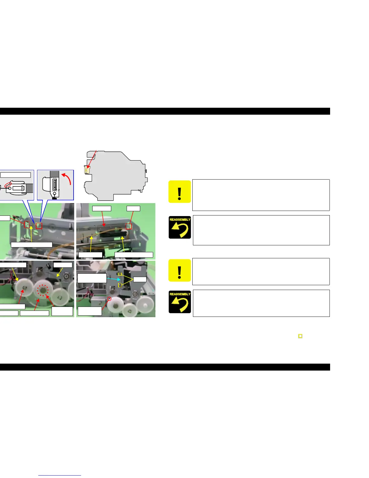
4.3.17 Carriage Unit
V External View (1)
Figure 4-39. Carriage Unit Removal (1)
V Part/Unit that should be removed before removing Carriage Unit.
Document Cover / Paper Support Assy. / Scanner Unit / Panel Unit /
Housing Upper / Printer Mechanism / Main Board Unit / CR Guide Frame /
CR motor
V Removal procedure
1. Release Timing Belt from Driven Pulley Holder.
2. Remove CR Scale from Main Frame.
3. Peel off PF Scale secured to Spur Gear 32.4 with the double-sided tape (x1).
4. Remove Spacer (4.1x0.5) for securing Spur Gear 30.8, and then remove Spur
Gear 30.8 from Main Frame.
5. Release CR Guide Shaft Torsion Spring from the hooks (x2, ) of Main
Frame, and then remove CR Guide Shaft Torsion Spring from Main Frame.
Driven Pulley HolderTiming Belt
CR Scale Hook
Extension Spring 3.289
Hook
Notch Location
CR Encoder Sensor Slot
Spacer (4.1x0.5)
Spur Gear 30.8
PF Scale
Left side
Double side
tape
Spur Gear 32.4
CR Guide Shaft
Torsion Spring
Installation
Hole
Hooks
CAUTION
Be cautious of the following points.
T Do not touch CR Scale with bare hands.
T Do not damage CR Scale.
T Handle leg of Extension Spring 3.289 in a way that does not
extend it.
T Extension Spring 3.289 should not be twisted.
T Install CR Scale so that it passes through the slit of CR Encoder
Sensor.
T Install the left end of CR Scale so that the cut section faces
upward.
CAUTION
Be cautious of the following points.
T Do not touch PF Scale with bare hands.
T Do not damage PF Scale.
PF Scale should not be unsteady.

 Loading...


