EPSON Stylus CX3500/CX3600/CX3650/CX4500/CX4600 Revision A
TROUBLESHOOTING Overview 80
3.1 Overview
This chapter describes unit-level troubleshooting. Refer to the flowchart in this chapter
to identify the defective unit and perform component level repair if necessary. This
chapter also explains motor coil resistance, sensor specification and error indication.
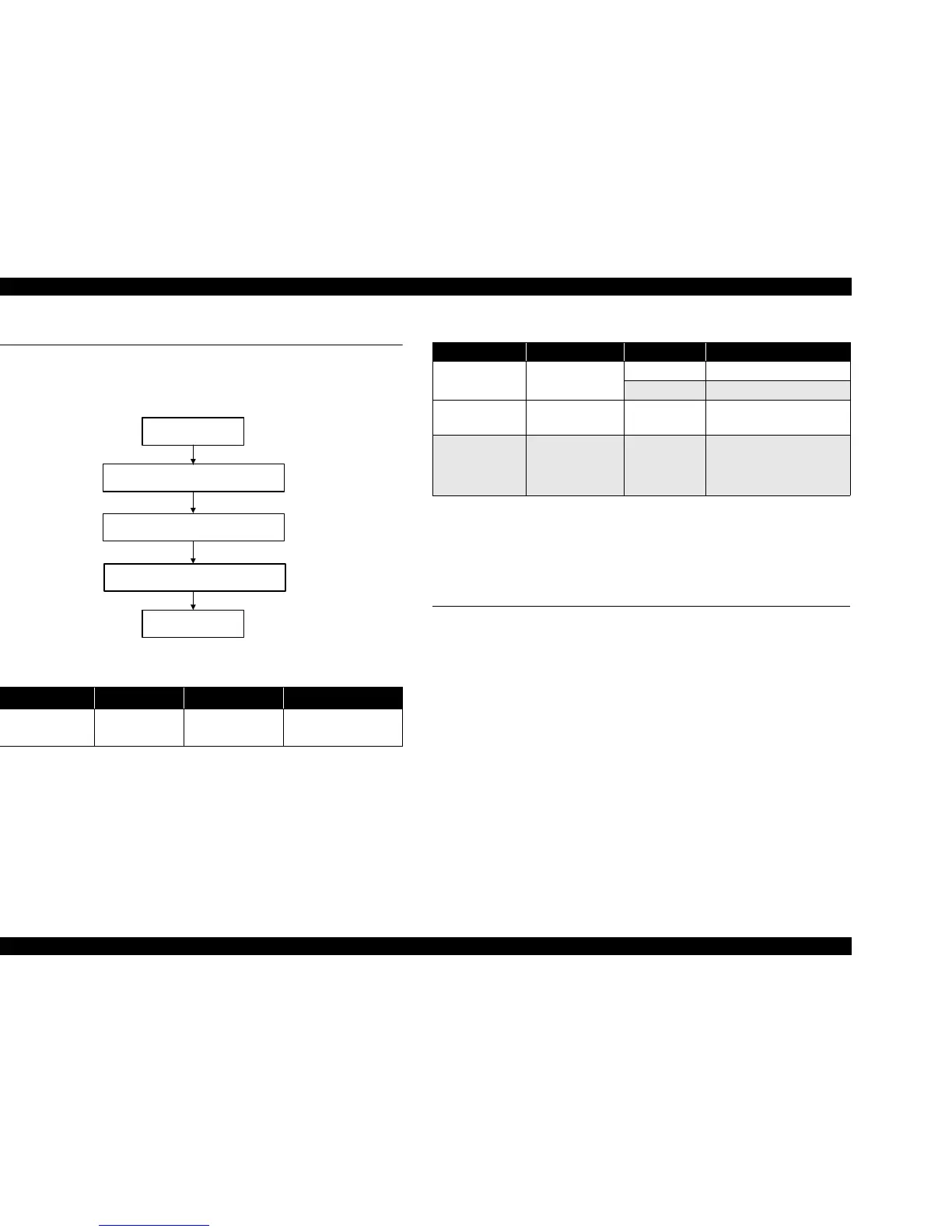
Figure 3-1. Troubleshooting flowchart
Note : Since CR Motor and PF Motor are DC motors, the resistance among the electric poles
varies. Therefore, judge if it is normal or abnormal based on if there is operation of the
motor or not; the resistance values cannot be used to judge the abnormality. However, it
is difficult to judge accurately, if it is not clear, replace the motor.
3.2 Error Indications and Fault Occurrence
Causes
This section describes the LED indications, STM3 messages and fault occurrence
causes at occurrence of the following errors during any sequence/operation (e.g.
power-on sequence, paper feeding/loading sequence, ink sucking sequence).
NOTE: The explanations for STM3 of the Stylus CX3500/CX3600/CX3650 are
the same as the Stylus CX4500/CX4600 completely except the followings.
1) SPC name (SPC: Scanner/Printer/Copier)
2) Figure of the SPC
3) T-code for each ink cartridge (refer to
Table 1-13 (p.18))
Table 3-1. Motor, coil resistance
Motor Location Check point Resistance
Scanner motor CN10
Pin 1 and 3
Pin 2 and 4
37Ω ± 7%
(at 25
°C / phase)
START
Unit-level troubleshooting
Unit repair
Assemble & Adjustment
END
Table 3-2. Sensor check point
Sensor name Check point Signal level Switch mode
PE Sensor CN3 / Pin 1 and 2
Less than 0.4V Off: No paper
More than 2.4V On : Detect the paper
PG Sensor CN4 / Pin 1 and 2 —
On : PG large
Off: PG normal
Scanner HP Sensor CN13 / Pin 1 and 2 —
On : Within Scanner Carriage
home position
Off: Out of Scanner Carriage
home position

 Loading...


