EPSON Stylus CX3500/CX3600/CX3650/CX4500/CX4600 Revision A
DISASSEMBLY AND ASSEMBLY Disassembly 126
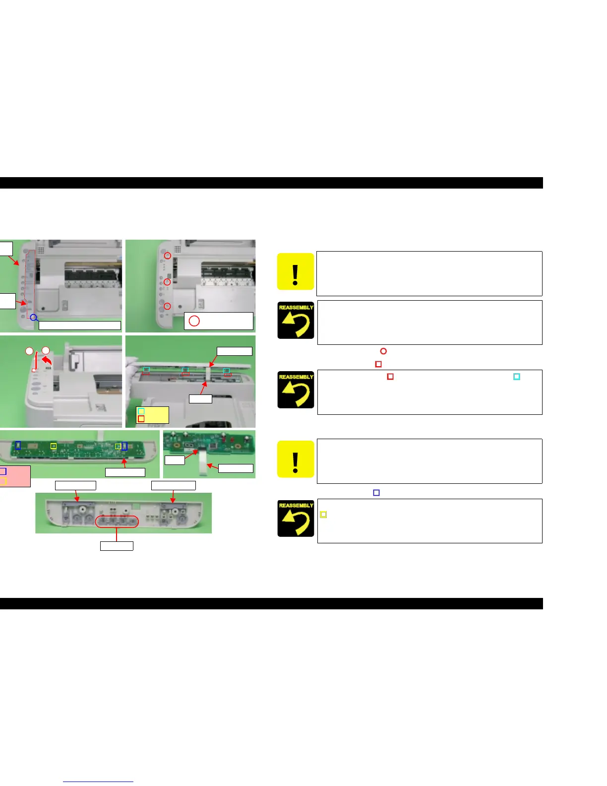
4.3.5 Panel Unit
V External View
Figure 4-13. Panel Unit Removal
V Part/Unit that should be removed before removing Panel Unit.
Document Cover / Scanner Unit
V Removal procedure
1. Peel off Panel Sheet from Panel Unit by using a precision screwdriver (-).
2. Remove the screws (x3, ) for securing Panel Unit.
3. Release the hooks (x3, ) of Panel Unit in order shown by figure.
4. Release Panel FFC from connector (CN12) of Main Board, and then remove
Panel Unit.
5. Release the hooks (x2, ) securing Panel Board, and then remove Panel Board.
6. Remove FFC from connector (CN1) of Panel Board.
7. Remove S-Buttons (x4), Copy-Button and Power-Button from Panel Housing.
(Stylus CX4500/CX4600 equipped with 5 S-Buttons.)
Panel FFC
CN12
Hooks
Notches
Panel
Sheet
Panel
Unit
Screwdriver insertion position
1
2
Panel Board
C.B.S 3x6 F/Zn
(7±1kgfcm)
CN1
Panel FFC
Power-ButtonCopy-Button
S-Buttons
Hooks
Dowels
CAUTION
When peeling off Panel Sheet, free it by inserting the screwdriver at
the place shown by the figure.
Paste new Panel Sheet to Panel Unit.
Align the hooks (x3, ) of Panel Unit with the notches (x3, ) of
Housing Upper.
CAUTION
When removing Panel Unit, Panel FFC will be hard to insert when
disconnecting it from Panel Board side (CN1).
Align the positioning holes (x2) of Panel Board with the dowels (x2,
) of Panel Housing.

 Loading...


