EPSON Stylus CX3500/CX3600/CX3650/CX4500/CX4600 Revision A
DISASSEMBLY AND ASSEMBLY Disassembly 133
4.3.9 PS Board Unit
V External View
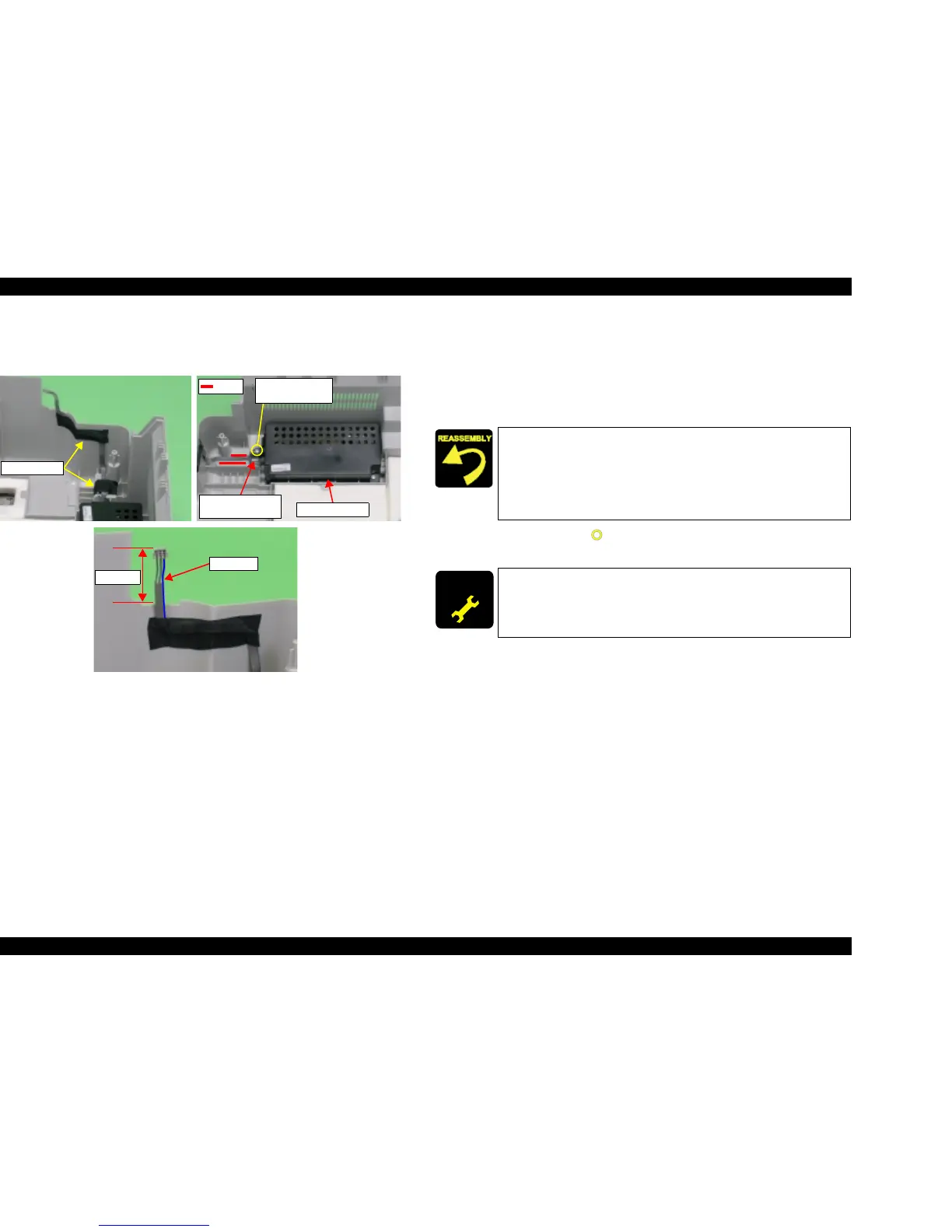
Figure 4-21. PS Board Unit Removal
V Part/Unit that should be removed before removing PS Board Unit.
Document Cover / Paper Support Assy. / Scanner Unit / Panel Unit /
Housing Upper / Printer Mechanism
V Removal procedure
1. Peel off the acetate tapes (x2) for securing PS Connector Cable.
2. Remove the screw (x1, ) for securing PS Board Unit, and then remove PS
Board Unit.
Acetate tapes
C.B.P 3x10 F/Zn
(4±1kgfcm)
Ferrite Core and
Cavity
Ribs
PS Board Unit
40±2mm
Blue line
T Set Ferrite Core into cavity of Housing Lower.
T Place PS Connector Cable between the ribs of Housing Lower.
T Leave PS Connector Cable projecting 40±2mm from the edge of
Housing Lower.
T Face the blue line of PS Connector Cable to the rear side of
Housing Lower.
ADJUSTM ENT
REQUIRED
When having replaced PS Board Unit, implement the following
adjustment. (Refer to Chapter 5 “ADJUSTMENT”)
T CR motor heat protection control

 Loading...


