EPSON Stylus CX3500/CX3600/CX3650/CX4500/CX4600 Revision A
DISASSEMBLY AND ASSEMBLY Disassembly 141
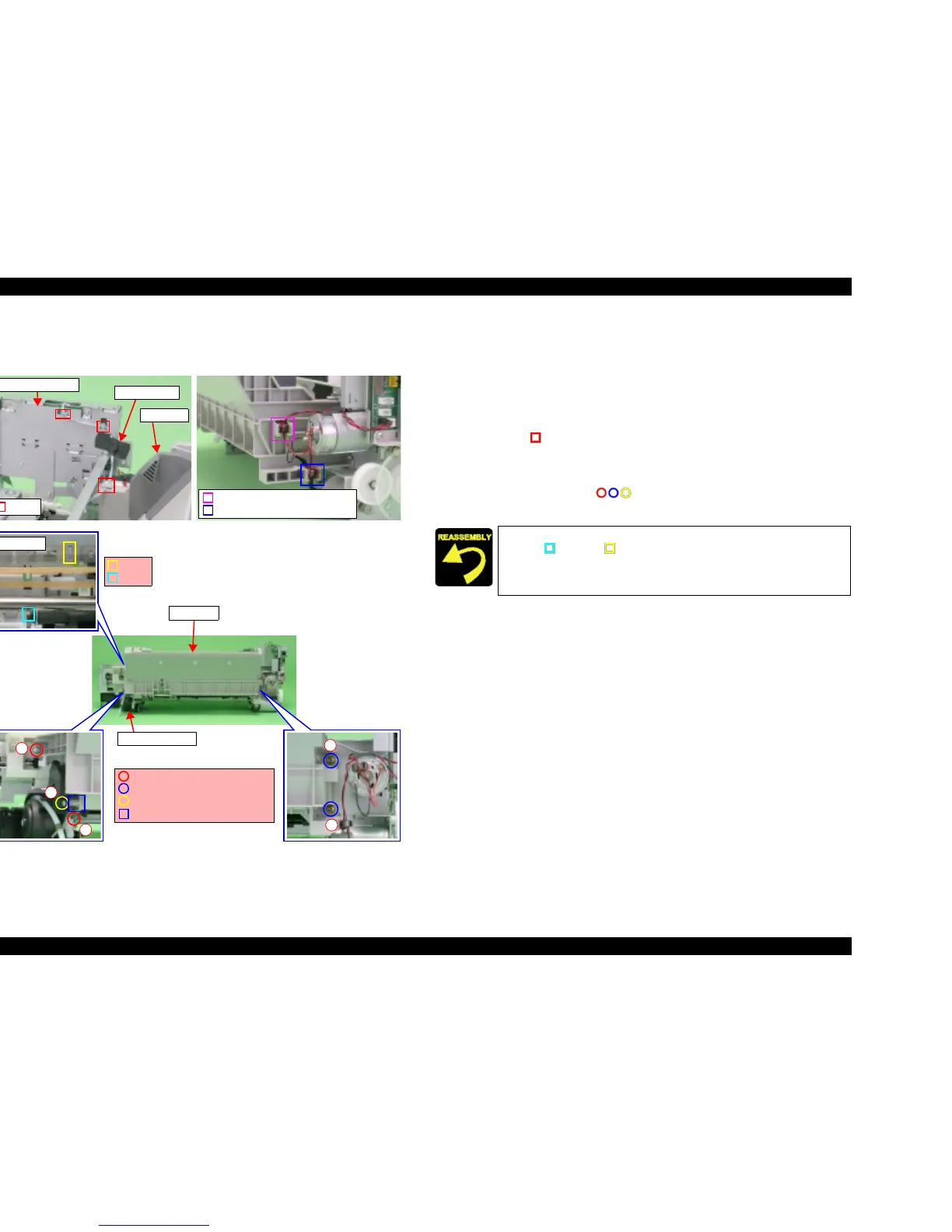
4.3.12 ASF Unit
V External View (1)
Figure 4-29. ASF Unit Removal (1)
V Part/Unit that should be removed before removing ASF Unit.
Document Cover / Paper Support Assy. / Scanner Unit / Panel Unit /
Housing Upper / Printer Mechanism
V Removal procedure
1. Peel off the acetate tape (x1) for securing PE Sensor Connector Cable to the
shield plate of Main Board, and then release PE Sensor Connector Cable from
hooks (x3, ) of ASF Unit and Main Board Unit.
2. Remove Ferrite Core of CR/PF Motor Connector Cable from slot of ASF
Unit.
3. Remove the screws (x5, ) for securing ASF Unit, and then remove
ASF Unit from Printer Mechanism.
Ferrite core (CR Motor) and Slot
Ferrite core (PF Motor) and Slot
1
4
5
2
3
ASF Unit
C.B.S 3x6 F/Zn (7±1kgfcm)
C.B.S (P2) 3x6 F/Zn (7±1kgfcm)
C.B.P 3x8 F/Zn (4±1kgfcm)
Shaft
Ink System Unit
Front side
Rib
Hooks
Acetate tape
Main Board Unit
ASF Unit
Dowel
T Align the positioning hole (x1) of Main Frame with the dowel
(x1, )/rib (x1, ) of ASF Unit.
T Insert the shaft of ASF Unit into the slot of Ink System Unit.
T Tighten the screws in order shown by figure.

 Loading...


