EPSON Stylus CX3500/CX3600/CX3650/CX4500/CX4600 Revision A
DISASSEMBLY AND ASSEMBLY Disassembly 152
4.3.18 Paper Guide Upper Unit
V External View
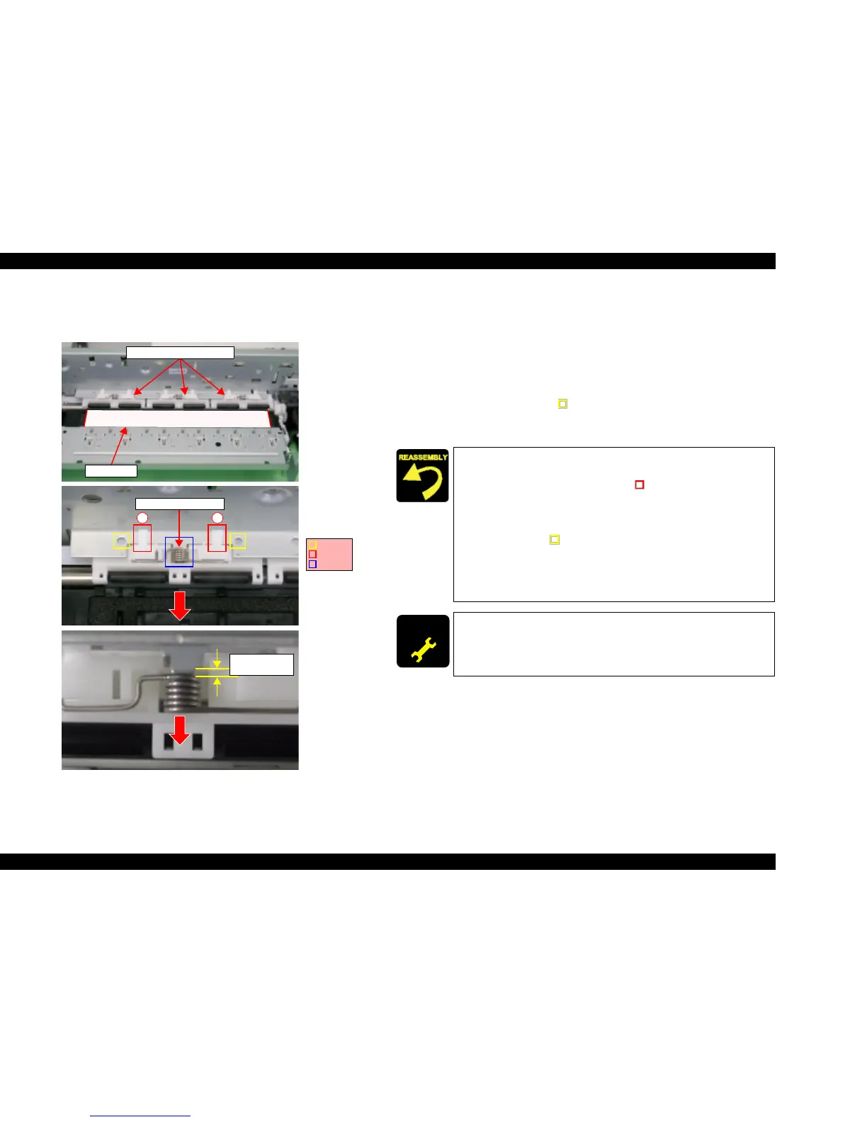
Figure 4-42. Paper Guide Upper Unit Removal
V Part/Unit that should be removed before removing Paper Guide Upper Unit.
Document Cover / Paper Support Assy. / Scanner Unit / Panel Unit /
Housing Upper / Print Head/ Printer Mechanism / Main Board Unit /
CR Guide Frame / CR motor / Carriage Unit
V Removal procedure
1. Set an OHP sheet.
2. Release the dowels (2 each, ) for securing Paper Guide Upper Unit (x3),
and then remove Paper Guide Upper Unit (x3) along with Torsion Spring
75.35 (1 each) from Main Frame.
OHP sheet
Paper Guide Upper Units
12
Torsion Spring 75.35
Dowels
Hooks
Rib
Approx.
1~1.5mm
Reassembly of Paper Guide Upper Unit
1. Set Torsion Spring 75.35 onto Paper Guide Upper Unit.
2. Temporarily place hooks (x2, ) of Paper Guide Upper
Unit onto Main Frame in order shown by figure.
3. Insert the coil section of Torsion Spring 75.35 into the rib.
4. Align the positioning holes (x2) of Main Frame with the
dowels (x2, ) of Paper Guide Upper Unit, and then set
Paper Guide Upper Unit along with Torsion Spring 75.35.
5. Pull the coil section of Torsion Spring 75.35 toward the
front, hold the margin at approximately 1~1.5mm, and then
eliminate gap with Paper Guide Upper Unit.
ADJUSTM ENT
REQUIRED
When having removed or replaced Paper Guide Upper Unit,
implement the adjustment in the following order. (Refer to Chapter
5 “ADJUSTMENT”)
T Top margin adjustment

 Loading...


