EPSON Stylus CX3500/CX3600/CX3650/CX4500/CX4600 Revision A
DISASSEMBLY AND ASSEMBLY Disassembly 154
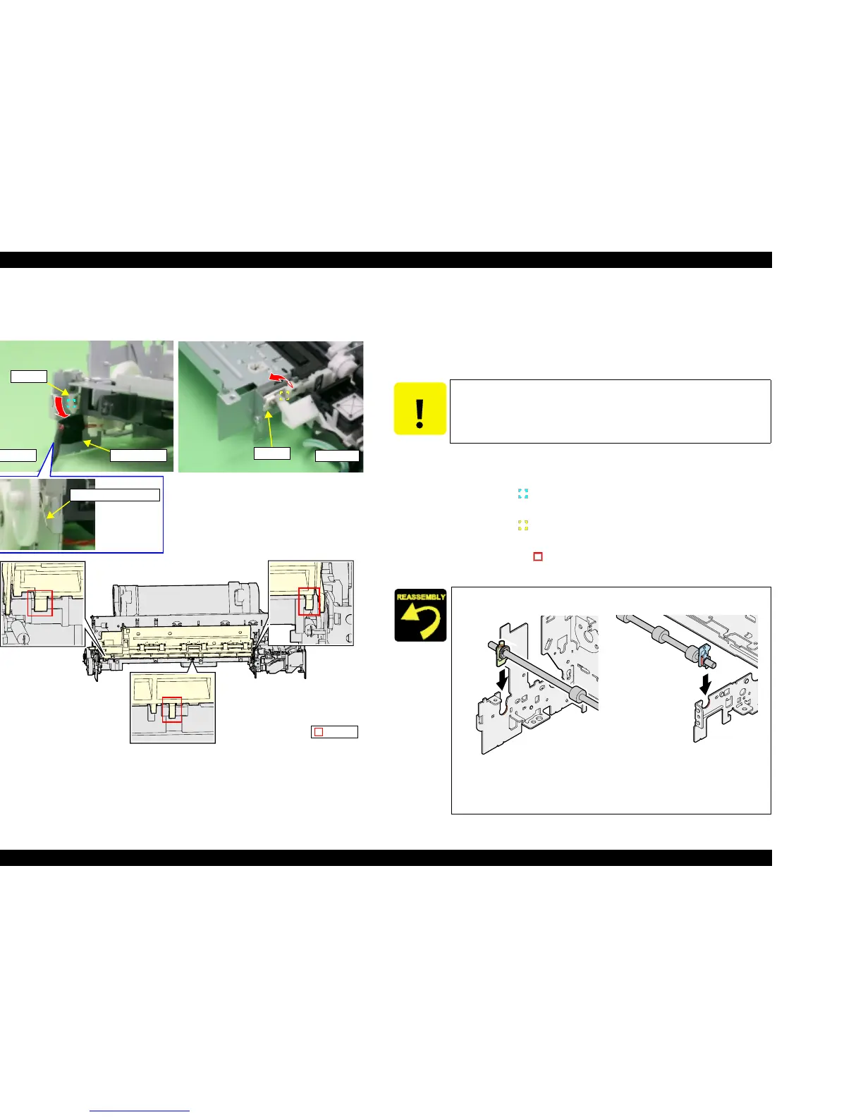
4.3.20 EJ Frame Unit
V External View (1)
Figure 4-44. EJ Frame Unit Removal (1)
V Part/Unit that should be removed before removing EJ Frame Unit.
Document Cover / Paper Support Assy. / Scanner Unit / Panel Unit /
Housing Upper / Print Head/ Printer Mechanism / Main Board Unit /
CR Guide Frame / CR motor / Carriage Unit / Front Frame
V Removal procedure
1. Peel off the acetate tape (x1) for securing PG Sensor Connector Cable.
2. Remove EJ Grounding Spring from the left end of EJ Frame Unit.
3. Release dowel (x1, ) of the left Bush 5 of EJ Frame Unit, and rotate
downward 90°.
4. Release dowel (x1, ) of Bush 5 at right end of EJ Frame Unit, and allow to
rotate upward (or downward) 90
°.
5. Release the hooks (x3, ) for securing EJ Frame Unit while lifting the front
side of EJ Frame Unit upward.
Right side
Bush 5
Left side
Bush 5
Acetate tape
EJ Grounding Spring
Hooks
CAUTION
T Do not hold FJ Frame Unit while handling Printer Mechanism
in your repair.
T Do not touch the rubber portion.
T Firmly insert left/right Bush 5 into the notches of Main Frame.
Figure 4-45. Installation of Bush 5
T Make sure that there is no gap between EJ Frame Unit and
Main Frame.
Left side Right side

 Loading...


