EPSON Stylus CX3500/CX3600/CX3650/CX4500/CX4600 Revision A
DISASSEMBLY AND ASSEMBLY Disassembly 143
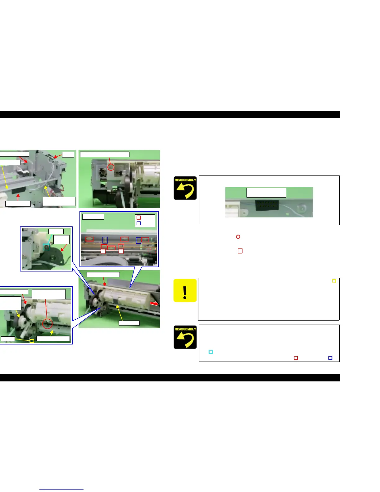
4.3.13 Holder Shaft Unit
V External View (1)
Figure 4-31. Holder Shaft Unit Removal (1)
V Part/Unit that should be removed before removing Holder Shaft Unit.
Document Cover / Paper Support Assy. / Scanner Unit / Panel Unit /
Housing Upper / Printer Mechanism / ASF Unit
V Removal procedure
1. Slide Carriage Unit center of printer.
2. Peel off the acetate tape (x1) for securing PE Sensor Connector Cable from
Main Frame.
3. Disconnect PE Sensor Connector Cable from connector (CN3) of Main Board.
4. Remove the screw (x1, ) for securing Holder Shaft Unit.
5. Remove Holder Shaft Unit from Main Frame as belows.
1. Push the hooks (x2, ) of Holder Shaft Unit, and pull Holder Shaft Unit
upward slightly from Main Frame.
2. Move Pump Unit to home position side slightly while holing the whole of
Holder Shaft Unit, and pull the bottom of the unit toward the backside of
the printer.
Holder Shaft Unit
LD Roller
CN3
PE Sensor
Connector Cable
Main Frame
Main Board Unit
Acetate tape
C.B.S 3x6 F/Zn (7±1kgfcm)
Front side
Hooks
Ribs
11
Dowel
Pump
Frame
Spur Gear 36.8
Combination
Gear
27.2, 19.2
Paper Guide Rear
PE Sensor Lever
and Notch
Hook
Use acetate tape to attach PF Sensor Connector Cable to printed line
position on Main Frame.
Figure 4-32. Installation of Timing Belt
CAUTION
T Damage may occur by placing a load on lower side hook (x1, )
of Pump Frame if Pump Frame is spread too wide.
T Do not touch LD Roller.
T Do not allow damage to gear surface of Spur Gear 36.82 and
Combination Gear 27.2, 19.2.
T Do not allow PE Sensor Lever to be damaged by interference
with Paper Guide Rear.
T Set PE Sensor Lever into notch of Paper Guide Rear.
T Engage gear surfaces of Spur Gear 36.8 and Combination Gear
27.2, 19.2.
T Align the positioning hole (x1) of Ink System with the dowel (x1,
) of Holder Shaft Unit.
T Secure Holder Shaft Unit with hooks (x6, ) and ribs (x2, ).
Printed Lines
(Installation Position)
1

 Loading...


