EPSON Stylus CX3500/CX3600/CX3650/CX4500/CX4600 Revision A
DISASSEMBLY AND ASSEMBLY Disassembly 142
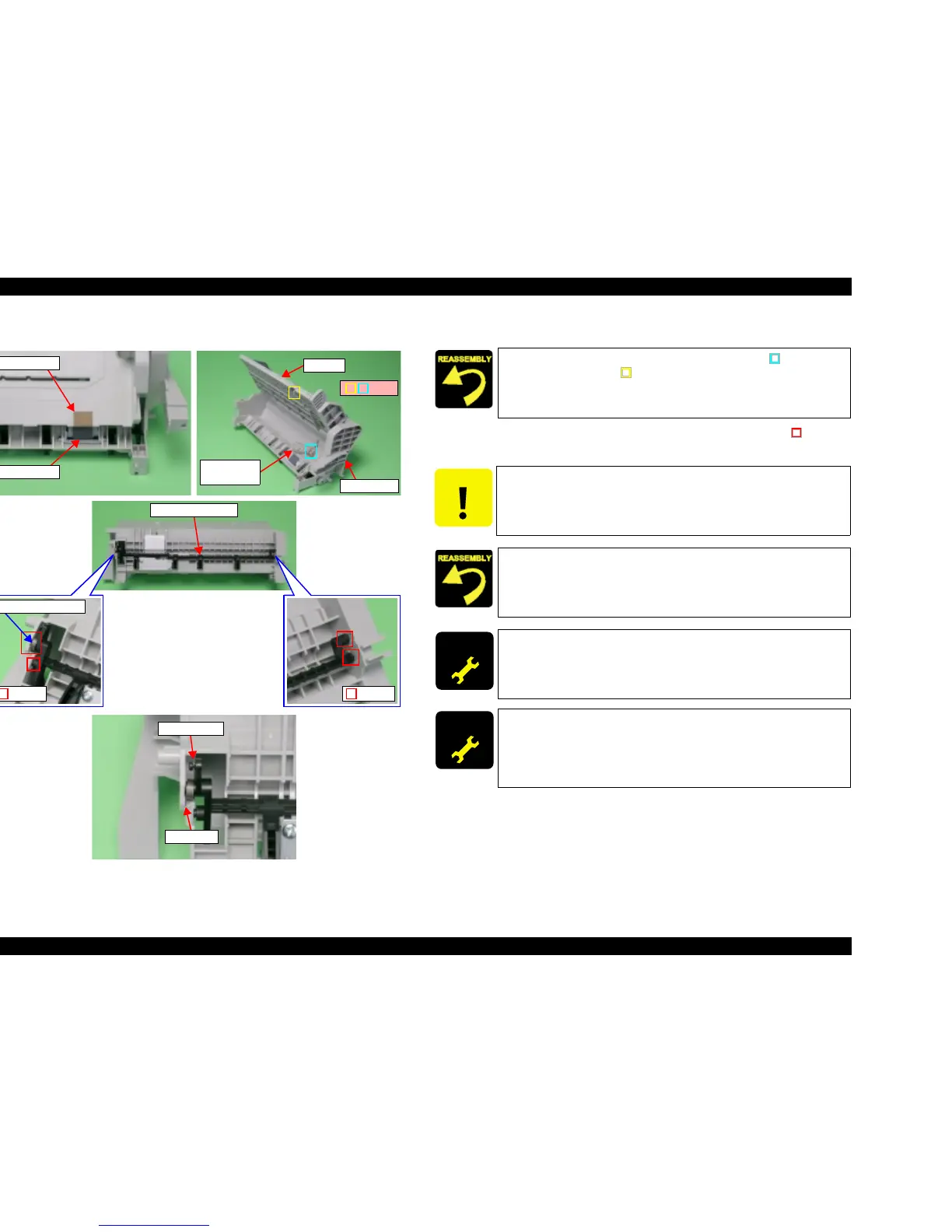
V External View (2)
Figure 4-30. ASF Unit Removal (2)
4. Open Hopper, and then remove Compression Spring 5.58.
5. Bend Paper Back Lever, release the both ends of dowels (2 each, ) from
ASF Unit, and then remove Paper Back Lever and Torsion Spring 6.45.
Paper Back Lever
Dowels
Torsion Spring 6.45
Dowels
Compression
Spring 5.58
Hopper
ASF Frame
Ribs
Retard Roller
Hopper Pad
L-Shape Leg
Short Leg
Install Compression Spring 5.58 to into the ribs (x2, ) of ASF
Frame and the rib (x1, ) of Hopper.
CAUTION
Do not touch Retard Roller and Hopper Pad.
T Fasten L-shape leg of Torsion Spring 6.45 to the shaft of Paper
Back Lever, and then fasten short leg to the channel of ASF
Unit.
T Confirm that Paper Back Lever operates smoothly.
ADJUSTM ENT
REQUIRED
After changing the ASF Unit for a new one, always apply grease G-
26 and grease G-46 to the specified portions.
T Refer to Chapter 6, Figure 6-5 (p.177)
ADJUSTM ENT
REQUIRED
When having removed or replaced ASF Unit, implement the
adjustment in the following order. (Refer to Chapter 5
“ADJUSTMENT”)
1. Top margin adjustment
2. First dot adjustment

 Loading...


