EPSON Stylus CX3500/CX3600/CX3650/CX4500/CX4600 Revision A
DISASSEMBLY AND ASSEMBLY Disassembly 156
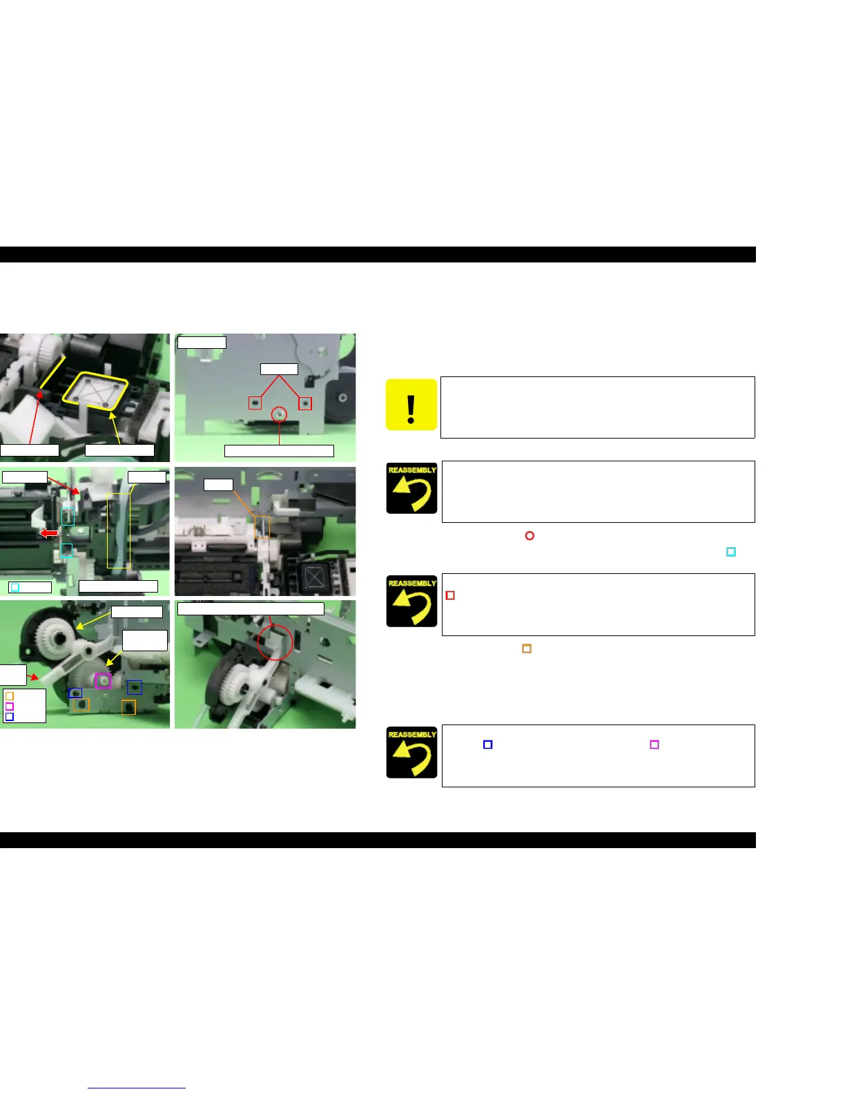
4.3.21 Ink System Unit
V External View
Figure 4-47. Ink System Unit Removal
V Part/Unit that should be removed before removing Ink System Unit.
Document Cover / Paper Support Assy. / Scanner Unit / Panel Unit /
Housing Upper / Print Head/ Printer Mechanism / Main Board Unit /
ASF Unit / Holder Shaft Unit / CR Guide Frame / CR motor / Carriage Unit /
Front Frame
V Removal procedure
1. Release Ink Tube located under Cap Frame.
2. Remove the screw (x1, ) for securing Cap Unit.
3. Slide Cap Unit to Main Frame interior, and then release the hooks (x2, ) of
Cap Unit from Main Frame.
4. Release the hooks (x3, ) for securing Pump Unit to Main Frame carefully,
and remove Pump Unit with supporting Change Lever and Combination Gear
27.2, 19.2 by your finger. (Supporting of Change Lever and gear is to prevent
damage by dropping in disassembly.)
5. Remove the whole of Ink System Unit from Printer Mechanism, and remove
the gears (x4) and the Pump Pulley.
Dowels
Right side
C.B.P 3x8 F/Zn (4±1kgfcm)
Sealing RubberHead Cleaner
Right bottom side
Hooks
Cap Unit Groove
Hook
Pump Unit
Change
Lever
Dowel
Dowels
Spur Gear
27.2
Hooks
Notch and Carriage Lock Location
CAUTION
T Do not cause damage by touching Sealing Rubber or Head
Cleaner when performing the following steps.
T Mark the connection location before removing Ink Tube.
Set by inserting Ink Tube into groove.
Align the positioning holes (x2) of Main Frame with the dowels (x2,
) of Cap Unit.
T Align the positioning holes (x3) of Main Frame with the dowels
(x2, ) of Pump Unit and the dowel (x1, ) of Spur Gear 27.2.
T Confirm that Cap Unit operates smoothly.

 Loading...


