EPSON Stylus CX3500/CX3600/CX3650/CX4500/CX4600 Revision A
DISASSEMBLY AND ASSEMBLY Disassembly 144
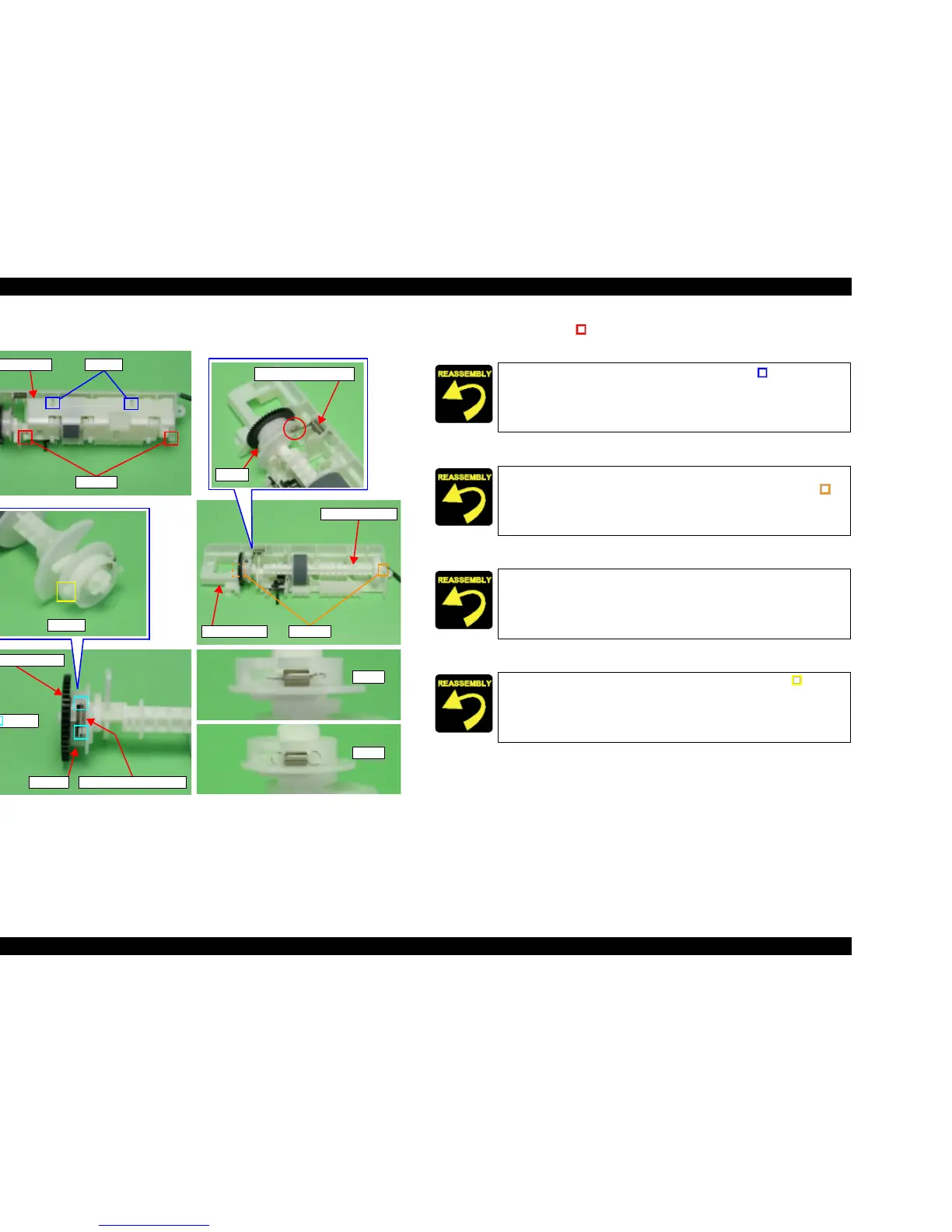
V External View (2)
Figure 4-33. Holder Shaft Unit Removal (2)
6. Release dowels (x2, ) for securing Paper Block to Holder Shaft, and then
remove Paper Block.
7. Remove LD Roller Shaft along with Clutch mechanism from Holder Shaft.
8. Remove Spur Gear 36.8 from LD Roller Shaft.
9. Remove Extension Spring 0.143, and remove Clutch from LD Roller Shaft.
Spur Gear 36.8
Clutch
Extension Spring 0.143
Hooks
Dowels
LD Roller Shaft
Holder Shaft
Torsion Spring 137.7
Cam
Paper Block
Dowels
Shafts
Dowel
O.K.
N.G.
Align notches (x2) of Paper Block with shafts (x2, ) of Holder
Shaft.
T Use leg of Torsion Spring 137.7 to press cam of LD Roller Shaft.
T Align positioning hole (x2) of Holder Shaft with dowel (x2, ) of
LD Roller Shaft.
Confirm that Clutch mechanism operates smoothly.
T Align positioning hole (x1) of Clutch with dowel (x1, ) of LD
Roller Shaft.
T Install Extension Spring 0.143 in the correct condition as shown
by figure.

 Loading...


