EPSON Stylus CX3500/CX3600/CX3650/CX4500/CX4600 Revision A
DISASSEMBLY AND ASSEMBLY Disassembly 145
V External View (3)
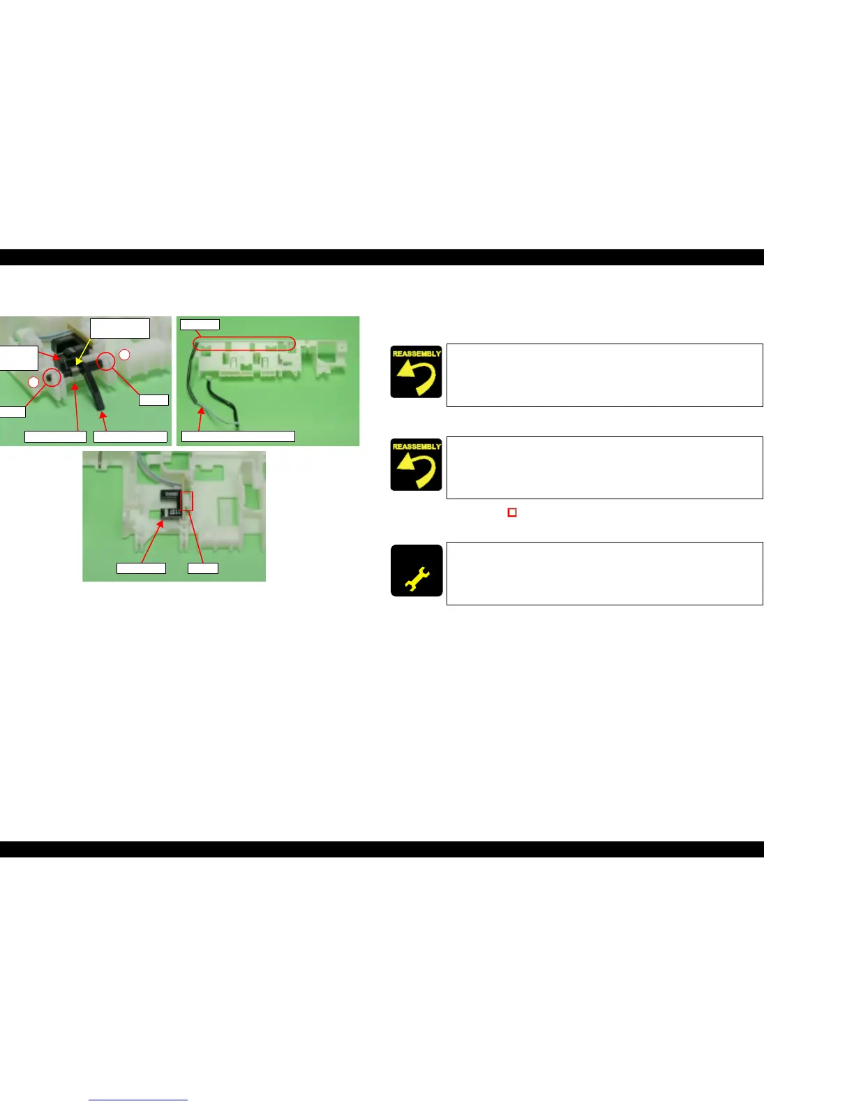
Figure 4-34. Holder Shaft Unit Removal (3)
10. Following order shown by figure, remove shaft of PE Sensor Lever from
Holder Shaft, and then remove PE Sensor Lever and Torsion Spring 0.22.
11. Remove Torsion Spring 0.22 from PE Sensor Lever.
12. Release PE sensor Connector Cable from channel of Holder Shaft.
13. Release hook (x1, ) for securing PE sensor, and then remove PE sensor
from Holder Shaft.
PE Sensor Lever
Shaft
Shaft
1
2
Straight Leg
L-Shape
Leg
Torsion Spring
0.22
PE Sensor Connector Cable
Channel
PE Sensor
Hook
T Fasten L-shaped leg of Torsion Spring 0.22 to indentation of PE
Sensor Lever, and fasten straight leg to Holder Shaft.
T Confirm that PE Sensor Lever operates smoothly.
Wrap PE Sensor Connector Cable so it will not protrude from
channel of Holder Shaft.
ADJUSTM ENT
REQUIRED
When having removed or replaced Holder Shaft Unit, implement
the adjustment in the following order. (Refer to Chapter 5
“ADJUSTMENT”)
T Top margin adjustment

 Loading...


