EPSON Stylus CX3500/CX3600/CX3650/CX4500/CX4600 Revision A
DISASSEMBLY AND ASSEMBLY Disassembly 151
V External View (3)
Figure 4-41. Carriage Unit Removal (3)
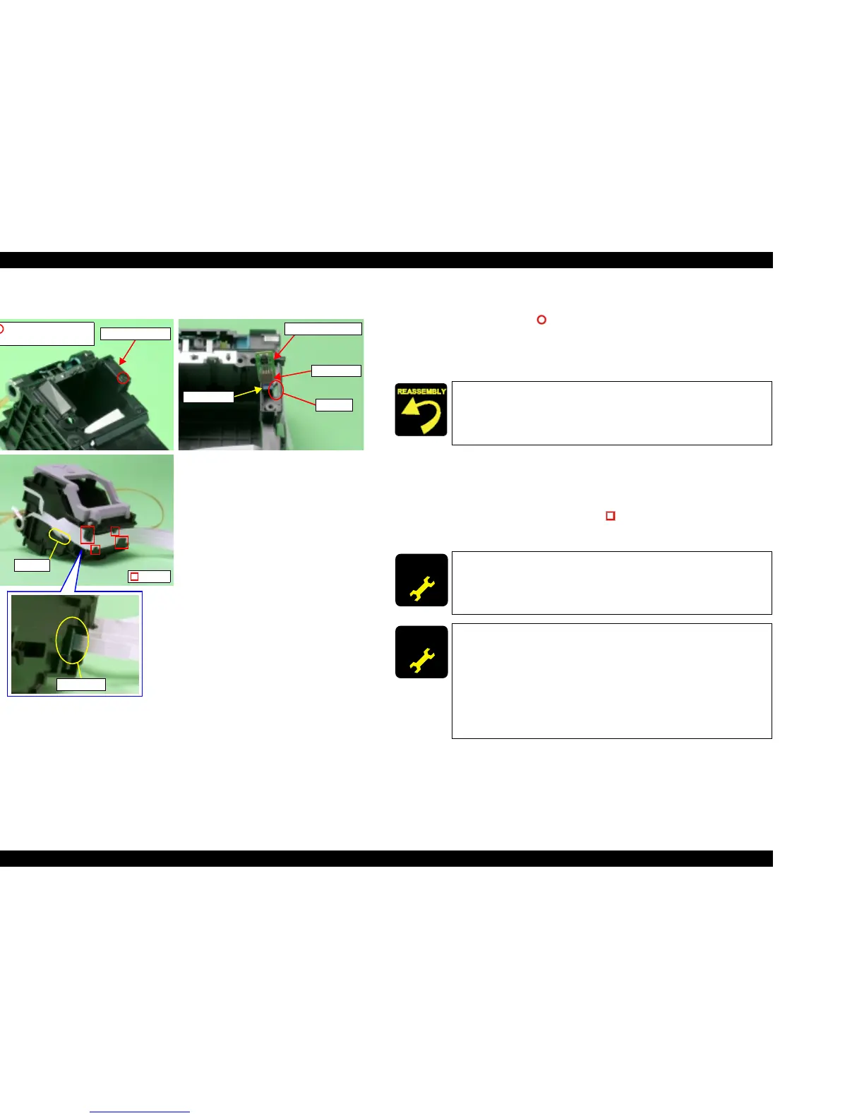
T PW Sensor Board Removal
1. Remove the screw (x1, ) for securing PW Sensor Cap, and then remove
PW Sensor Cap.
2. Disconnect Head FFC from the connector of PW Sensor Board, and then pull
out Head FFC from the notch of Carriage.
T Head FFC Removal
1. Remove Print Head from Carriage Unit.
2. Pull out Head FFC from the notch of Carriage.
3. Release Head FFC from the hooks (x4, ) for securing Head FFC.
4. Disconnect Head FFC from the connector of CSIC board.
PW Sensor Board
Connector
Head FFC
Notch
PW Sensor Cap
C.B.P (P1) 1.7x5 F/ZB
(2±0.5kgfcm)
Hooks
Notch
Connector
Do not allow PW Sensor Cap to float.
ADJUSTM ENT
REQUIRED
After changing the Carriage Unit for a new one, always apply
grease KEN to the specified portions.
T Refer to Chapter 6, Figure 6-7 (p.178)
ADJUSTM ENT
REQUIRED
When having replaced Carriage Unit, implement the adjustment in
the following order. (Refer to Chapter 5 “ADJUSTMENT”)
1. PG Adjustment
2. Top margin adjustment
3. Head angular adjustment
4. Bi-D adjustment
5. PW adjustment
6. First dot adjustment

 Loading...


