EPSON Stylus CX3500/CX3600/CX3650/CX4500/CX4600 Revision A
DISASSEMBLY AND ASSEMBLY Disassembly 125
V External View (5)
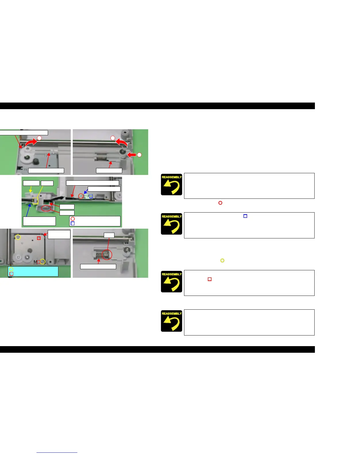
Figure 4-12. Scanner Motor Unit/Scanner HP Sensor/Driven Holder Removal
T Scanner Motor Unit/Scanner HP Sensor/Driven Holder Removal
1. Move Scanner Carriage Unit to the center.
2. Release Scanner Timing Belt from Combination Gear 22.8, 7.762 and Driven
Holder.
3. Release the shaft of Hinge L from the socket of Scanner Housing Lower.
4. Release Scanner Motor Connector Cable and Scanner HP Sensor Connector
Cable from the hook of Hinge L, and then pull from the notch of Scanner
Housing Lower.
5. Remove the screw (x1, ) for securing Scanner HP Sensor, and then remove
Scanner HP Sensor.
6. Release Scanner Motor Connector Cable and Scanner HP Sensor Connector
Cable from the hook of Scanner Housing Lower while holding Scanner
Carriage Shaft.
7. Remove the screws (x2, ) for securing Scanner Motor Unit, and then
remove Scanner Motor Unit.
8. Remove Driven Holder Spring from Scanner Housing Lower by using a
tweezers.
1
3
Driven Holder
Combination Gear 22.8, 7.762
2
Scanner Timing Belt
Hinge L
Scanner Motor Connector Cable
Notch
Hook
Scanner HP Sensor
Connector Cable
Scanner HP Sensor
C.B.P 3x8 F/Zn (5±1kgfcm)
Dowel
Shaft
Scanner
Motor Unit
C.B.P 3x8 F/Zn (5±1kgfcm)
Dowels
Rib
Driven Holder Spring
Place Scanner Motor Connector Cable and Scanner HP Sensor
Connector Cable as shown by figure.
Align the positioning hole (x1, ) of Scanner HP Sensor with the
dowel (x1) of Scanner Housing Lower.
Align the positioning holes (x2) of Scanner Motor Unit with the
dowels (x2, ) of Scanner Housing Lower.
Insert Driven Holder Spring into the rib of Driven Holder.

 Loading...


