EPSON Stylus CX3500/CX3600/CX3650/CX4500/CX4600 Revision A
DISASSEMBLY AND ASSEMBLY Disassembly 129
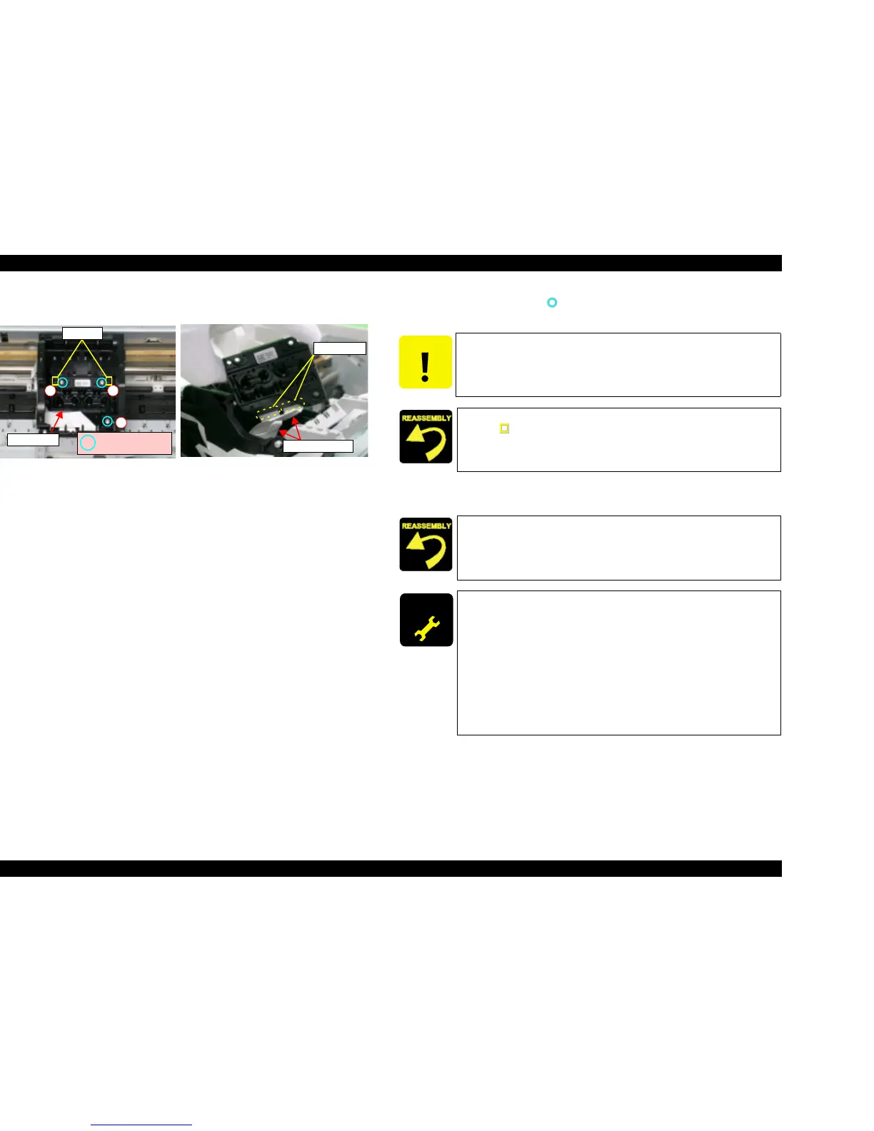
V External View (2)
Figure 4-17. Print Head Removal (2)
5. Remove the screws (x3, ) for securing Print Head, and then lift Print Head
by using a long-nose plier.
6. Disconnect Head FFCs (x2) from connectors (x2) of Print Head, and then
remove Print Head.
Print Head FFC
Connectors
Print Head
C.B.P 2.5x8 F/Zn
(3±1kgfcm)
Dowels
12
3
CAUTION
Use caution not to touch or damage the nozzles or the ink supply
needles of Print Head.
T Align the positioning holes (x2) of Print Head with the dowels
(x2, ) of Carriage Unit.
T Tighten the screws in order shown by figure.
Insert Head FFC firmly into the connector of Print Head.
ADJUSTM ENT
REQUIRED
When having removed or replaced Print Head, implement the
adjustment in the following order. (Refer to Chapter 5
“ADJUSTMENT”)
1. PG Adjustment
2. Ink charge (for replacement only)
3. Input Head ID (for replacement only)
4. Head angular adjustment
5. Bi-D adjustment
6. PW adjustment
7. First dot adjustment

 Loading...


