EPSON Stylus CX3500/CX3600/CX3650/CX4500/CX4600 Revision A
DISASSEMBLY AND ASSEMBLY Disassembly 160
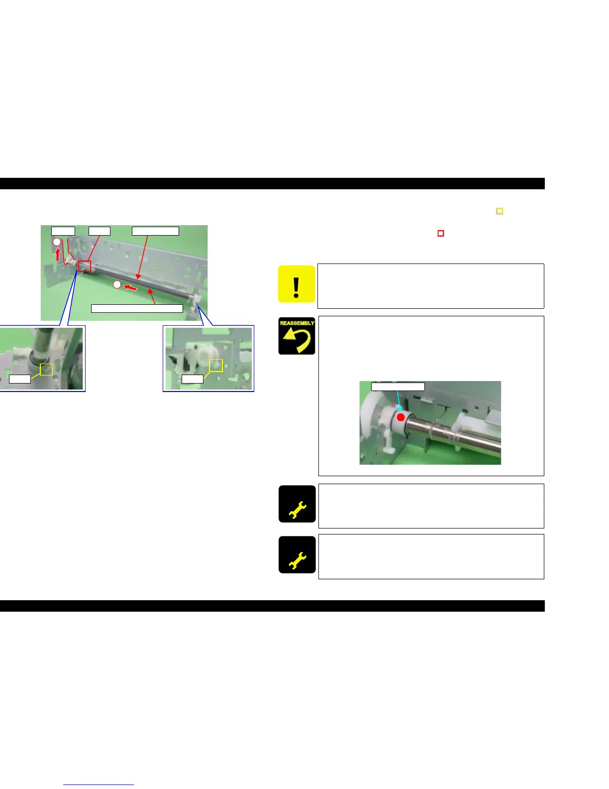
V External View (2)
Figure 4-51. PF Roller Unit Removal (2)
6. Sift PF Roller Unit to left, and then release the hooks (1 each, ) of Bush 10
(Left/Right).
7. Release PF Roller Unit from the hook (x1, ) at the left side of Paper Guide
Rear, and then remove PF Roller Unit along the notch at the left end of Main
Frame.
PF Roller UnitNotch
1
2
Hook
PF Roller Unit Coating Location
Hook Hook
CAUTION
Do not shift Bush 10 (Right) to coating location of PF Roller.
When replacing PF Roller Unit with a new component, be sure to
mark Bush 10 (Left) of PF Roller Unit with a red circle.
When replacing Main Board Unit with a refurbished unit,
determine the PF Roller production value if the EEPROM cannot be
backed up. (PF Roller Unit service parts are limited to IEI
products.)
Figure 4-52. Marking position
ADJUSTM ENT
REQUIRED
After changing the PF Roller Unit for a new one, always apply
grease G-26 to the specified portions.
T Refer to Chapter 6, Figure 6-13 (p.180) and Figure 6-14 (p.180)
ADJUSTM ENT
REQUIRED
When having replaced PF Roller Unit, implement the adjustment in
the following order. (Refer to Chapter 5 “ADJUSTMENT”)
1. PF Scale Sensor positioning adjustment
2. PF roller shaft manufacture code
Marking position

 Loading...


