Stylus Photo R1900/R2880/R2000/R2000s/SC-P400 Series Revision I
Stylus Photo R2000/R2000s Disassembly 191
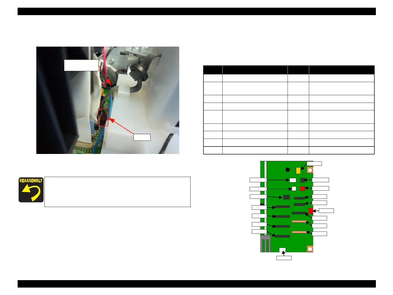
3. Disconnect the Wireless LAN Board cable, and remove the Wireless LAN
Board Assy.
Figure 8-14. Remove the Wireless LAN Board Assy (3)
Board Assy (Main Board / Power Supply Board)
For disassembling the Board Assy, please refer to
"4.3.1 Board Assy
(Main Board/Power Supply Board) (p86)"
.
Describes the Connector Layout of the Main Board to the following.
Table 8-15. Main Board Connector
Refer to
Figure 8-12
for routing the cables.
Don't forget to secure the earth cable of the PictBridge
Holder while securing the earth cable of the Wireless
LAN Board.
No. Connector No. Connector
CN1 PictBridge CN14 Head FFC
CN4 Panel Board, CDR Sensor, Cover
Open Sensor
CN22 CSIC
CN5 Relay FFC (for sensor) CN25 High Voltage Module
CN6 LED Board CN115 CR Motor
CN9 Ink Mark Sensor, CR Encoder
Sensor, PW Sensor
CN116 PF Motor
CN11 Head FFC CN117 Pump Motor
CN12 Head FFC CN118 APG Motor
CN13 Head FFC CN119 ASF Motor
CN2 Wireless LAN Board --- ---
Wireless LAN
Board Cable
CN2
CN1
CN116
CN118
CN5
CN6
CN2
CN4
CN11
CN12
CN25
CN22
CN9
CN14
CN13
CN117
CN115
CN119

 Loading...


