EPSON Stylus Photo R1900/R2880/R2000/R2000s/SC-P400 Series Revision I
Disassembly And Assembly Removing the Motors 131
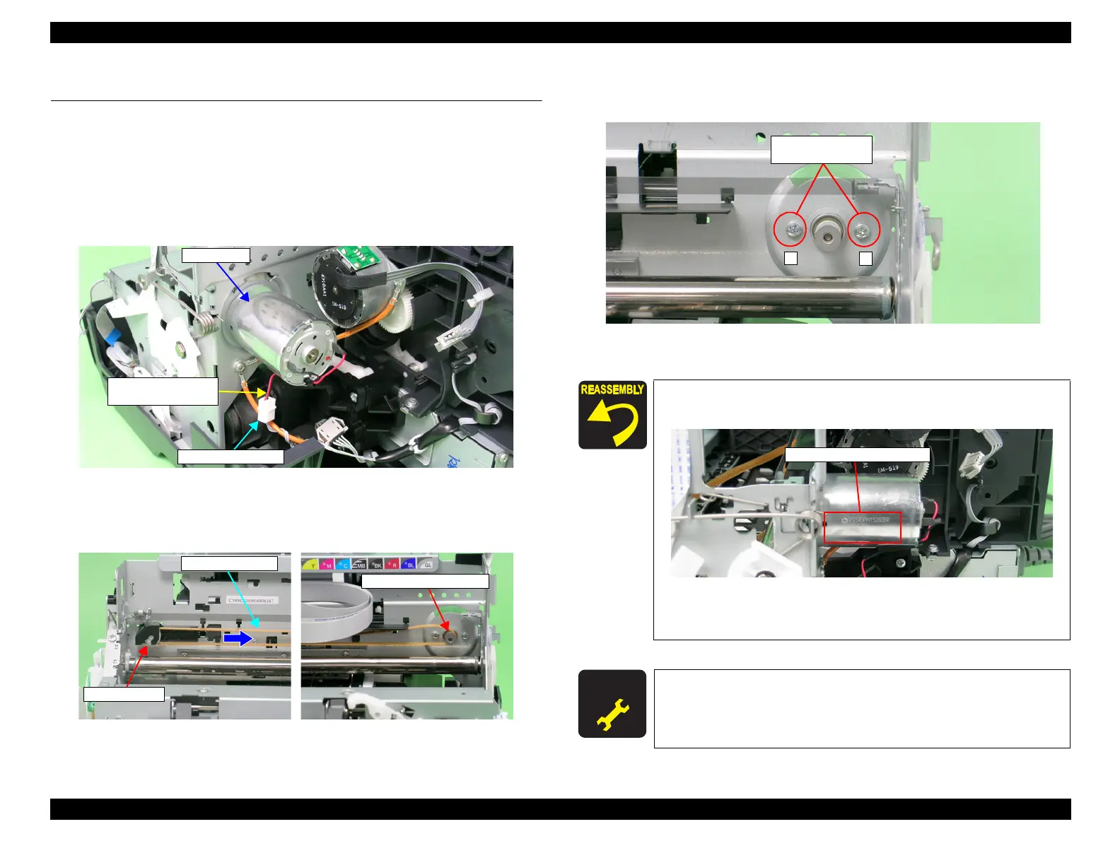
4.5 Removing the Motors
4.5.1 CR Motor
1. Remove the Upper Housing / Printer Cover. (p.83)
2. Release the Carriage Lock, and move the Carriage Unit to the center.
(Refer to 4.1.6
Locking/Unlocking the Carriage and Opening/Closing the CDR Tray Base (p.75))
3. Disconnect the CR Motor connector cable from the Relay connector.
Figure 4-157. Removing the CR Motor Connector Cable
4. Press the Driven Pulley toward the center to loosen the CR Drive Belt, and remove
the CR Drive Belt from the CR Motor Pinion Gear.
Figure 4-158. Removing the CR Motor
5. Remove the two C.B.S. M3 x 4 screws that secure the CR Motor, and remove the
CR Motor from the Main Frame.
Figure 4-159. Removing the CR Motor
CR Motor
Relay connector
CR Motor connector
cable
CR Drive Belt
Driven Pulley
Make the Lot No. printed surface on the CR Motor face the
direction shown in the figure below.
Figure 4-160. Reinstalling the CR Motor
Tighten the screws in the order shown in Figure 4-159
A D J U S T M E N T
R E Q U I R E D
After replacing the CR Motor, always make the required adjustments
referring to the following.
•“Chapter 5 Adjustment (p.139)”
2
1
10) C.B.S. M3x10
(4±0.5 kgf.cm)

 Loading...


