EPSON Stylus Photo R1900/R2880/R2000/R2000s/SC-P400 Series Revision I
Disassembly And Assembly Disassembling the Printer Mechanism 116
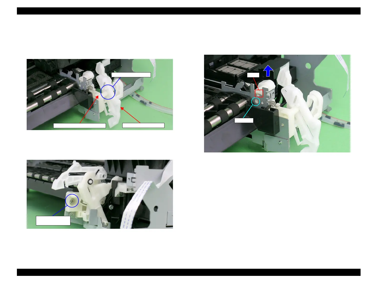
4.4.12 CDR Release Lever Sub Assy
1. Remove the Paper EJ Frame Assy / Front Cover / CDR Tray Base. (p.114)
2. Remove the Shaft on the Right CDR Release Base from the bushing on the CDR
Release Lever.
Figure 4-112. Removing the Right CDR Release Lever Sub Assy (1)
3. Remove the C.B.S. M3 x 6 screw that secures the Right CDR Release Lever Sub
Assy.
Figure 4-113. Removing the Right CDR Release Lever Sub Assy (2)
4. To prevent parts from dropping, refit the shaft on the Right CDR Release Base into
the CDR Release Lever.
5. Press the guide pin that secures the Right CDR Release Lever Sub Assy with
tweezers, and remove it upwards from the Main Frame.
Figure 4-114. Removing the Right CDR Release Lever Sub Assy (3)
CDR Release Lever
Shaft and Bushing
Right CDR Release Base
2) C.B.S. M3x6
(6±1 kgf.cm)

 Loading...


