EPSON Stylus Photo R1900/R2880/R2000/R2000s/SC-P400 Series Revision I
Disassembly And Assembly Disassembling the Printer Mechanism 117
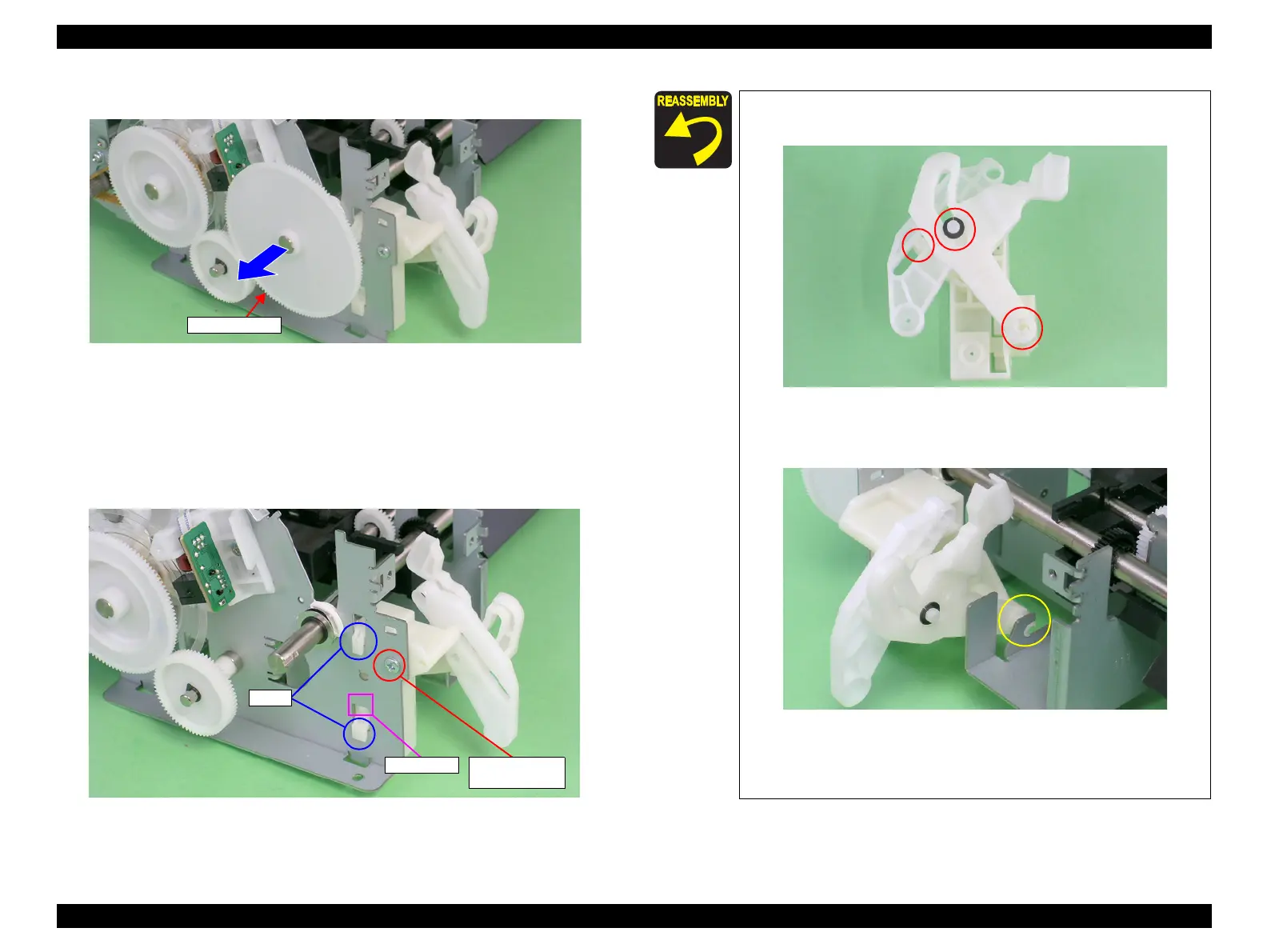
6. Remove the Spur Gear 68 from the Paper EJ Roller Shaft.
Figure 4-115. Removing the Spur Gear 68
7. Remove the C.B.P. M3 x 6 screw that secures the Left CDR Release Lever Sub
Assy.
8. Press the small tab of the Left CDR Release Lever Sub Assy with a flathead
screwdriver, and remove the Left CDR Release Lever Sub Assy upward from the
Main Frame.
Figure 4-116. Removing the Left CDR Release Lever Sub Assy
Tabs
Small tab 9) C.B.P. M3x6
(6±1 kgf.cm)
Make sure that the Left CDR Release Lever Sub Assy is
correctly assembled as shown in the figure below.
Figure 4-117. Reinstalling the Left CDR Release Lever Sub Assy (1)
Align the Shaft and Bushing.
Figure 4-118. Reinstalling the Left CDR Release Lever Sub Assy (2)
Align the two tabs on the Left CDR Release Lever Sub Assy with
the positioning holes on the Main Frame. (See Figure 4-116.)

 Loading...


