EPSON Stylus Photo R1900/R2880/R2000/R2000s/SC-P400 Series Revision I
Disassembly And Assembly Removing the Boards 86
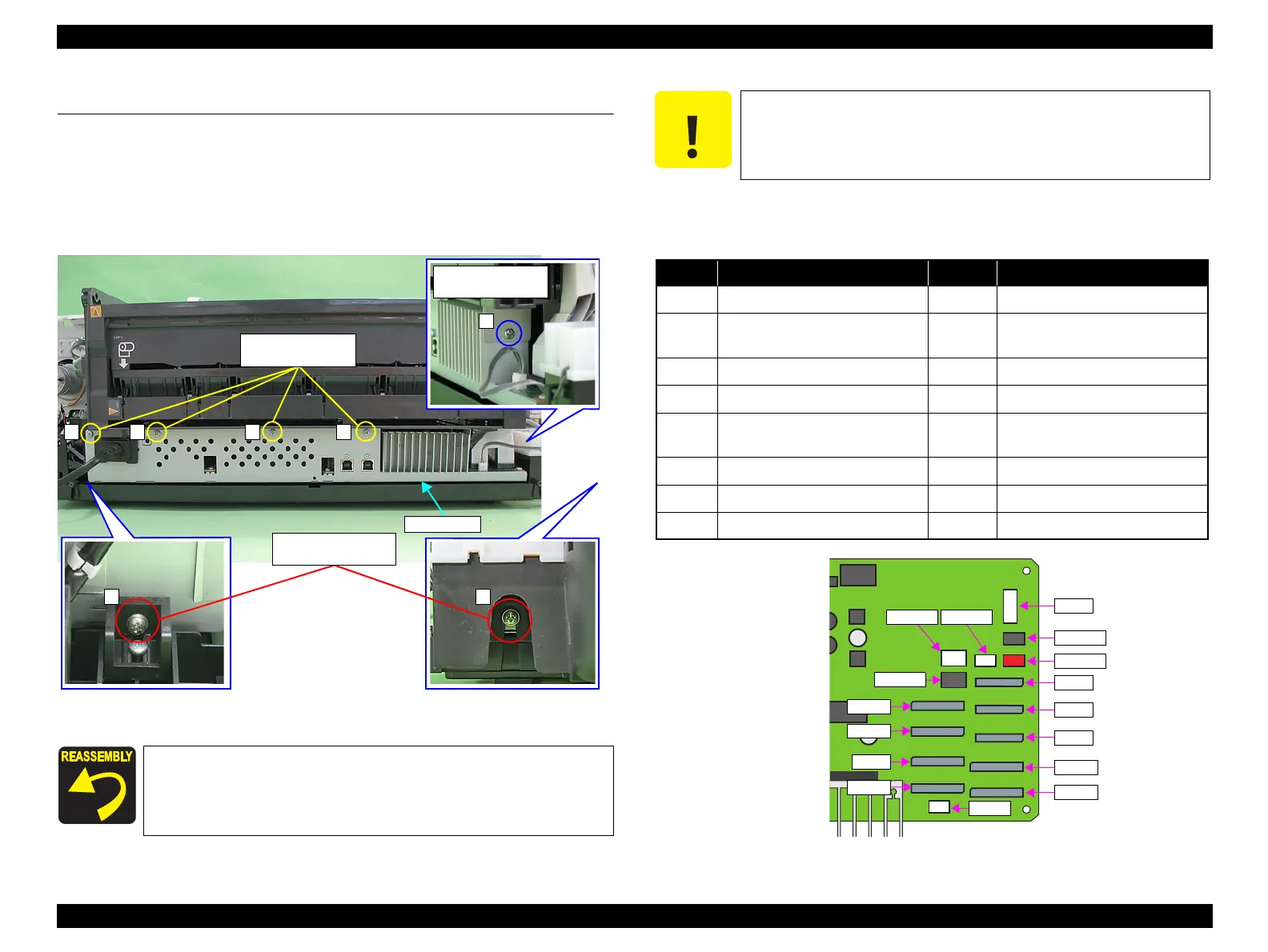
4.3 Removing the Boards
4.3.1 Board Assy (Main Board/Power Supply Board)
1. Remove the Upper Housing / Printer Cover. (p.83)
2. Remove the seven screws (four C.B.S. M3 x 6, two C.B.S. (P2) M3 x 10, and one
C.B.S. M3 x 10) that secure the Board Assy.
Figure 4-25. Removing the Board Assy (1)
3. Disconnect all the cables and FFCs connected on the Main Board from the near
side one by one.
Figure 4-26. Connector Layout of the Main Board (130 Digit Side)
Tighten the screws in the order shown in Figure 4-25.
3) C.B.S. (P2) M3x10
(6±1 kgf.cm)
2) C.B.S. M3x6
(8±1 kgf.cm)
1 3 4
14) C.B.S. M3x10
(8±1 kgf.cm)
7
When performing the following procedure, prevent the FFC and the
cables from being scratched. If having trouble disassembling, remove
the High Voltage Module Cover to make the work easier. (refer to
4.3.3 High Voltage Module Step2 (p89) .)
No. Connector No. Connector
CN1 PictBridge CN14 Head FFC
CN4 Panel Bard, CDR Sensor, Cover
Open Sensor
CN22 CSIC
CN5 Relay FFC (for sensor) CN25 High Voltage Module
CN6 LED Board CN115 CR Motor
CN9 Ink Mark Sensor, CR Encoder
Sensor, PW Sensor
CN116 PF Motor
CN11 Head FFC CN117 Pump Motor
CN12 Head FFC CN118 APG Motor
CN13 Head FFC CN119 ASF Motor
CN1
CN116
CN118
CN5
CN6
CN4
CN11
CN12
CN115
CN119
CN117
CN13
CN14
CN25
CN22
CN9

 Loading...


