EPSON Stylus Photo R1900/R2880/R2000/R2000s/SC-P400 Series Revision I
Disassembly And Assembly Removing the Boards 89
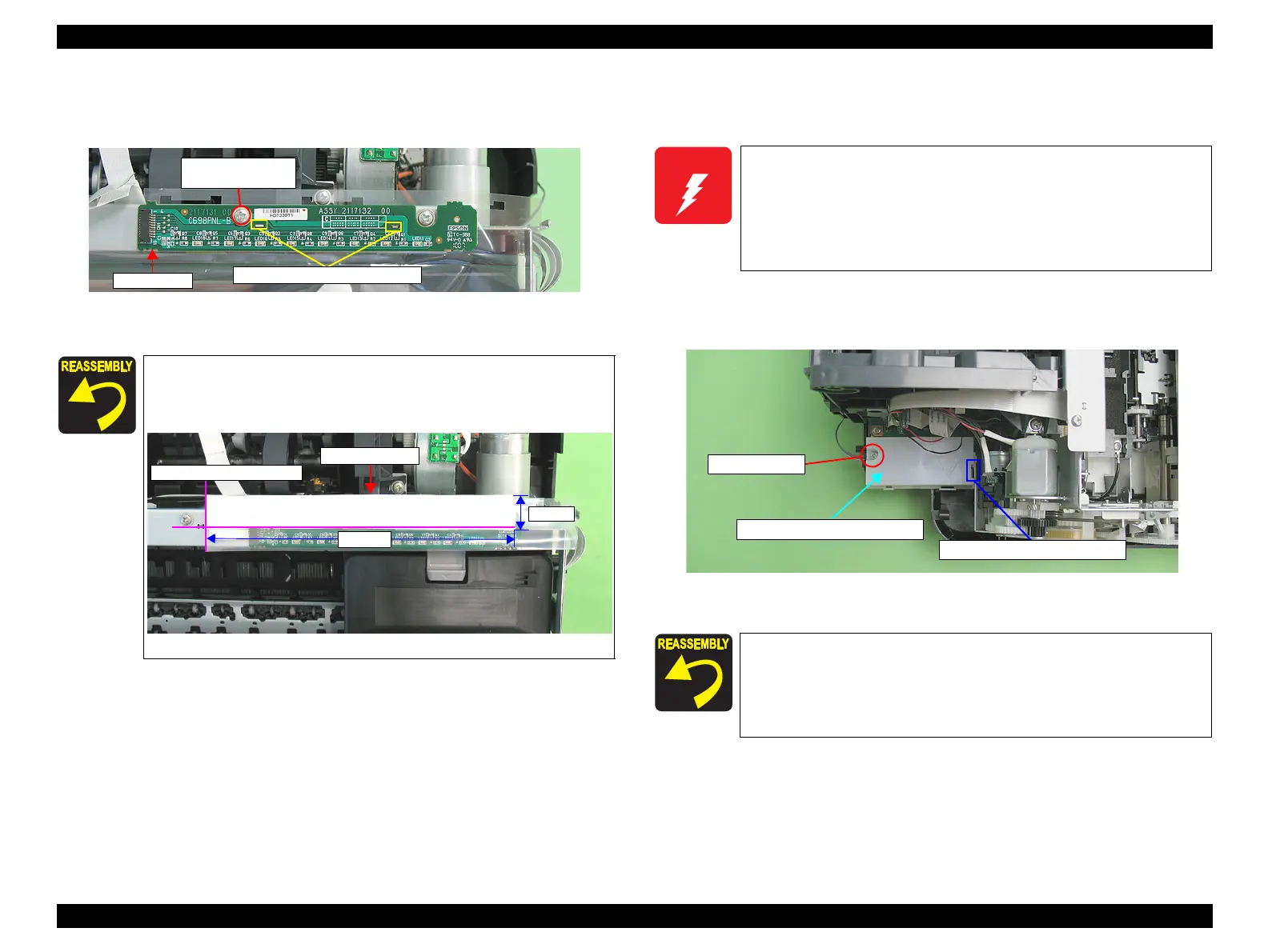
5. Remove the C.B.S. (P4) M3 x 8 screw that secures the LED Board, and remove
the LED Board.
Figure 4-35. Removing the LED Board (3)
-
4.3.3 High Voltage Module
1. Remove the Upper Housing / Printer Cover. (p.83)
2. Remove the C.B.P. M3 x 8 screw and remove the High Voltage Module Cover.
Figure 4-37. Removing the High Voltage Module Board (1)
Align the two tabs on the Upper Housing with the positioning
holes on the LED Board. (Refer to Figure 4-35.)
Attach acetate tape as shown in the figure below.
Figure 4-36. Reinstalling the LED Board
6) C.B.S. (P4) M3x8
(6±1 kgf.cm)
LED Board
Tabs and positioning holes
160mm
18mm
Attachment Position
Acetate Tape
High voltage is applied in the High Voltage Module. The following
must be strictly observed when you handle the High Voltage
Module.
Do not turn the power on with the Upper Housing removed.
To avoid electrical shock, do not make or leave the High
Voltage Module Board uncovered when applying a voltage.
Before tightening the screw, make sure to engage the hook of
the High Voltage Module Cover with the positioning hole on the
Lower Housing.
When installing the High Voltage Module Cover, be careful not
to trap any of the cables underneath the cover.
High Voltage Module Cover
Hook and Positioning hole
4) C.B.P. M3x8

 Loading...


