EPSON Stylus Photo R1900/R2880/R2000/R2000s/SC-P400 Series Revision I
Disassembly And Assembly Removing the Boards 90
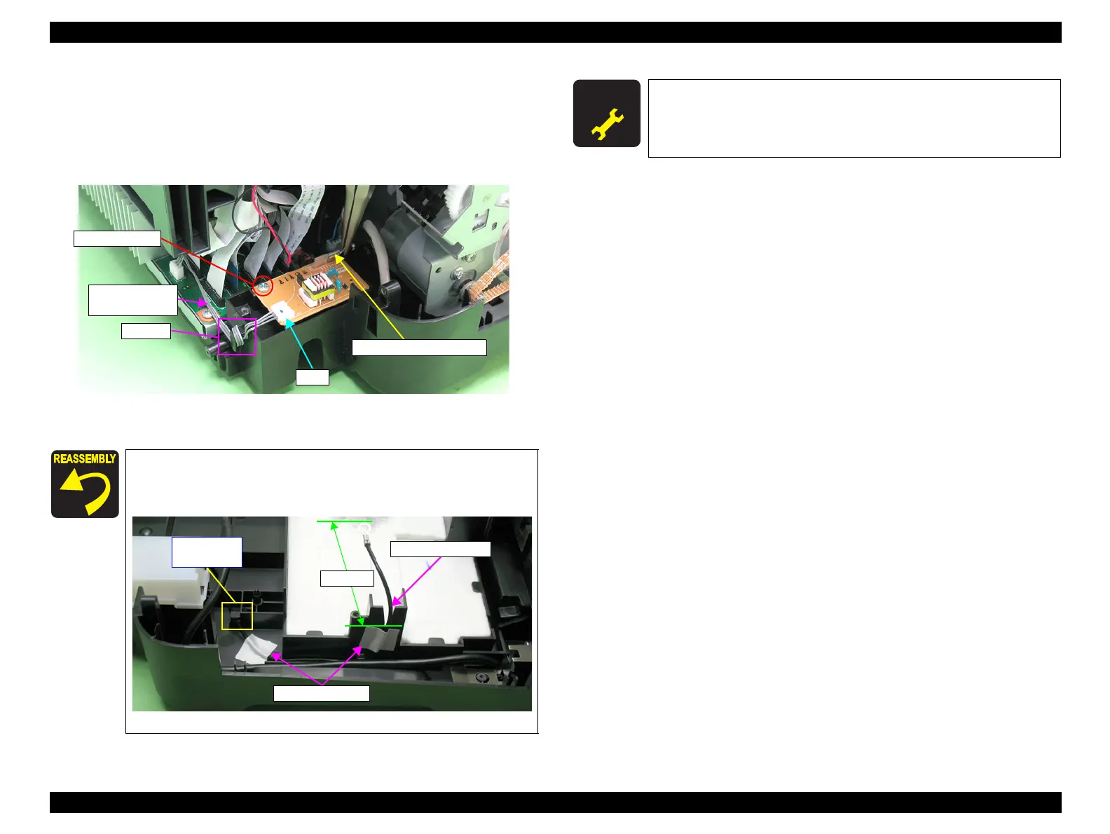
3. Pull off the connector of the electrode cable from its terminal on the High Voltage
Module Board with long-nose pliers or the like.
4. Disconnect the High Voltage Module cable from connector CN1 on the High
Voltage Module Board.
5. Remove the C.B.P. M3 x 8 screw and remove the High Voltage Module Board.
Figure 4-38. Removing the High Voltage Module Board (2)
Wind the High Voltage Module cable on the hook one time as
shown in Figure 4-38.
Route the electrode cable as shown in the figure below.
Figure 4-39. Routing the Electrode Cable
4) C.B.P. M3x8
High Voltage
Module cable
Hook
CN1
Electrode cable terminal
Acetate Tape
Wind it on
the hook.
Electrode cable
55±2mm
A D J U S T M E N T
R E Q U I R E D
After replacing the High Voltage Module, always make the required
adjustments referring to the following.
•“Chapter 5 Adjustment (p.139)”

 Loading...


