EPSON Stylus Photo R1900/R2880/R2000/R2000s/SC-P400 Series Revision I
Disassembly And Assembly Disassembling the Printer Mechanism 108
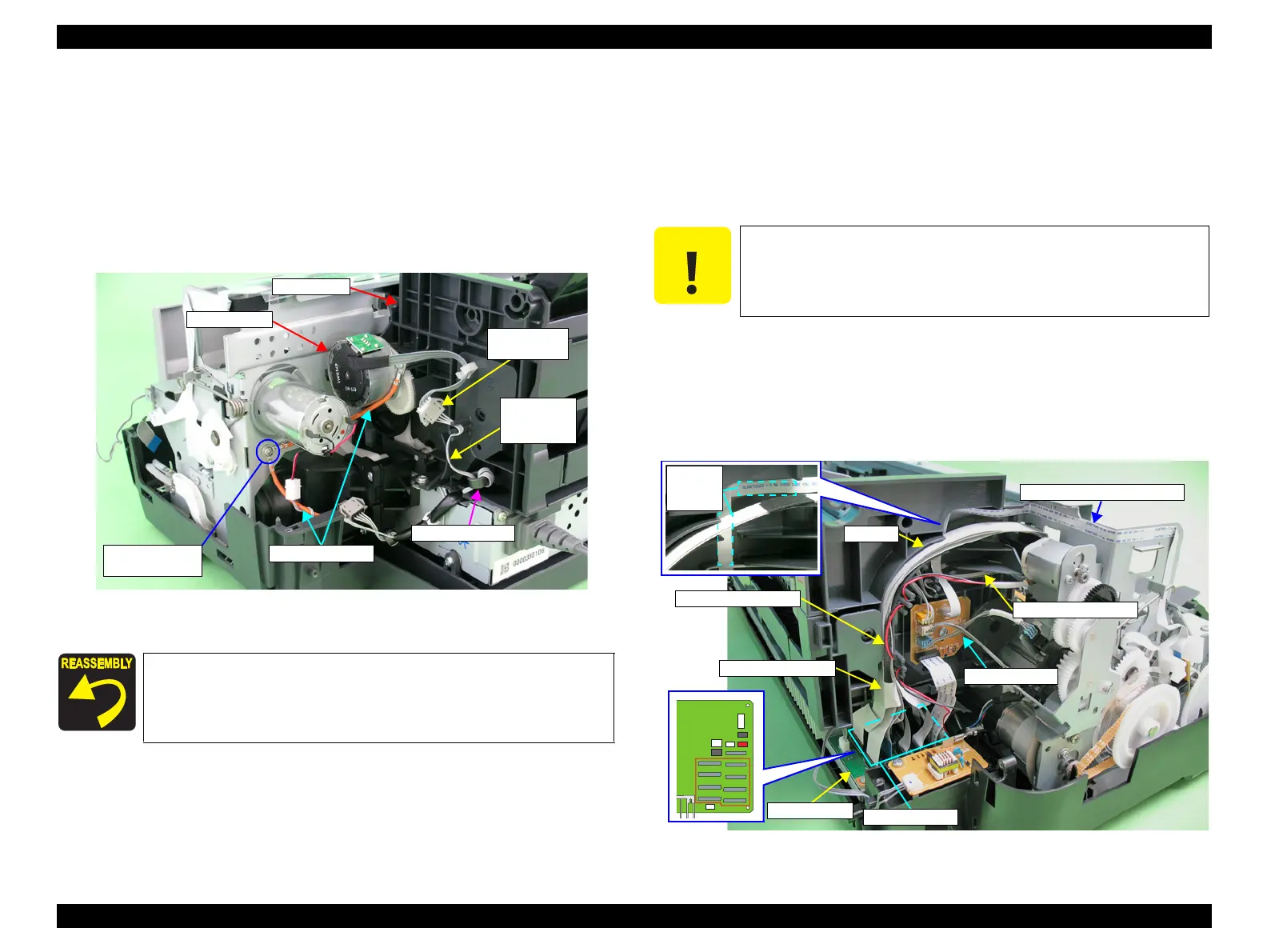
4.4.6 ASF Assy
1. Remove the Printer Mechanism. (Refer to 4.4.4 Lower Housing / Printer
Mechanism (p.98))
2. Remove the C.B.S. M3 x 8 screw that secures the Earth cables on the right rear
side of the printer, and remove the Earth cables.
3. Disconnect the ASF Motor connector from the Relay connector.
4. Disconnect the Relay connector cable from the ASF Assy.
Figure 4-92. Releasing the Cables (1)
5. Disconnect all the cables and the FFCs from the connectors on the Relay Board.
CN1 : Relay FFC
CN2 : PE Sensor cable
CN4 : APG Sensor cable (lower side)
CN5 : APG Sensor cable (upper side)
CN6 : PF Encoder Sensor FFC
6. Disconnect the FFC bundled by the acetate tape from the CN6 to CN22 on the
Main Board, and release it from the groove on the ASF Assy.
7. Disconnect the APG Motor cable and PE Sensor cable from the ASF Assy.
8. Peel off the PF Encoder FFC secured by two pieces of double-sided adhesive tape
from the ASF Assy.
Figure 4-93. Releasing the Cables (2)
Secure the two Earth cables together with the screw.
Referring to Figure 4-92, correctly route the Relay connector
cable.
5) C.B.S. M3x8
(8±1 kgf.cm)
Relay
connector
Earth cables
Relay
connector
cable
Ferrite Core
ASF Motor
ASF Assy
When performing the following steps, be extremely careful not to
damage the cables. If having trouble disassembling, remove the
High Voltage Module Cover to make the work easier. (refer to 4.3.3
High Voltage Module Step2 (p89) .)
Main Board
CN6 to CN22
Relay Board
PE Sensor cable
PF Encoder Sensor FFC
Groove
APG Motor cable
Acetate Tape

 Loading...


