T3-B T6-B Maintenance 7. Covers
40 T-B series Maintenance Manual Rev.1
7.4 Connector Plate
CAUTION
■
remove the connector plate forcibly. Unnecessary strain on cables may
result in damage to the cables, disconnection, and/or contact failure.
■
When installing the connector plate, be careful not to allow the cables to interfere
with the plate mounting an
d do not bend these cables forcibly to push them into
the cover. Unnecessary strain on cables may result in damage to the cables,
disconnection, and/or contact failure. When routing the cables, observe the cable
locations after removing the cover. Be sure
to place the cables back to their
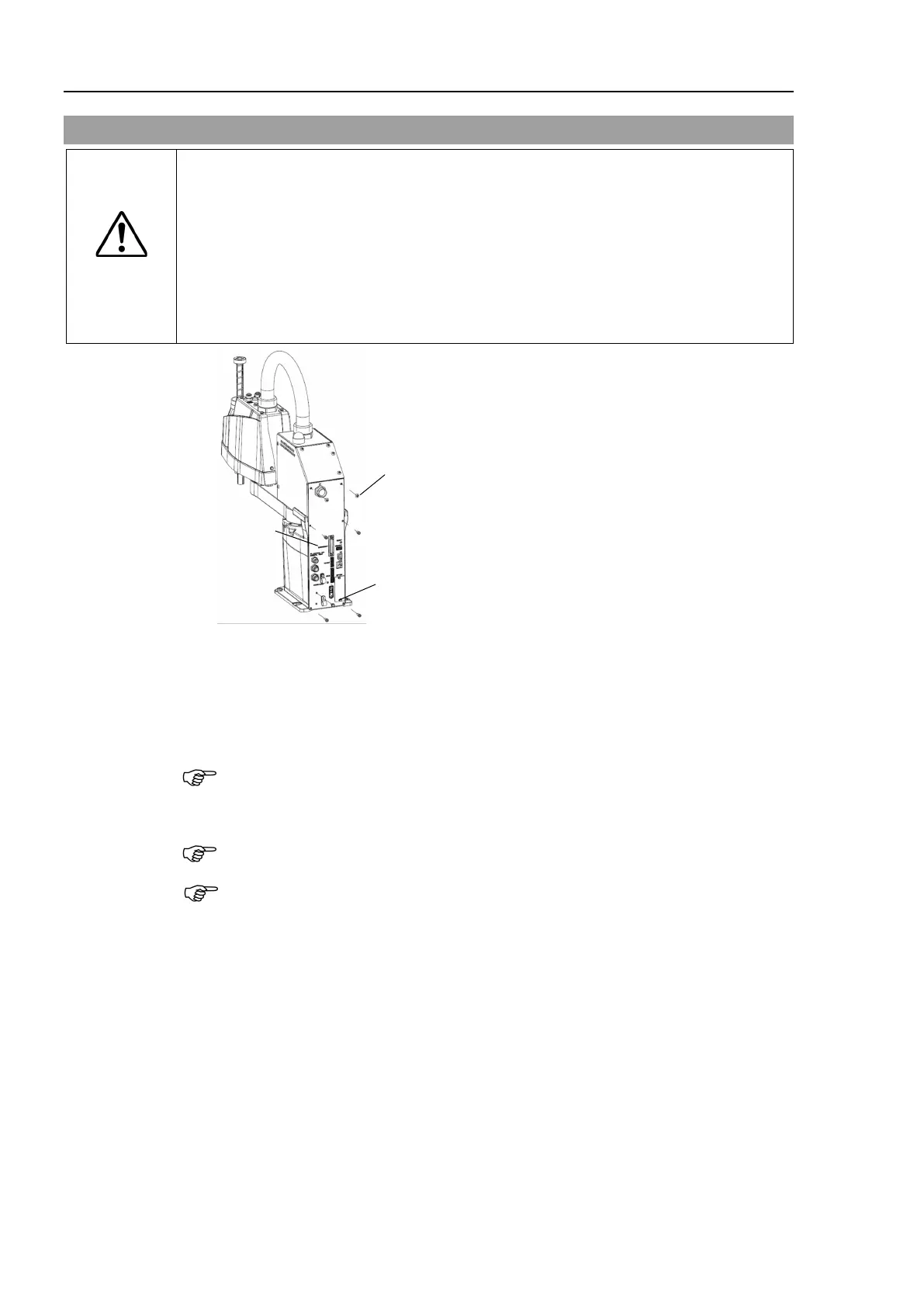
T3-B: 2-M4×6 Truss
+ 4-M4×10
T6-B: 4-M4×10 Hexagon socket head button bolt
M4×8 Sems
(For Clamps Fixing)
Connector
Plate
Removal
Remove the Power Cable Cover.
Reference 7.3 Power Cable Cover
Remove power cable clamp and
then remove power cable connector.
When removing the power cable connector, pull it out with pushing clips on both side
of the connector.
Unscrew the power cable cover mounting bolts and then remove the power cable cover.
same as power unit cover fixing bolts.
Position of the fittings and size of the connector plate are different between T6
-B and
-B. Position and size of screws is the common. The above illustration is T3-B.

 Loading...


