T3-B T6-B Maintenance 11. Joint #3
84 T-B series Maintenance Manual Rev.1
11.1 Replacing Joint #3 Motor
Maintenance
Motor 100W 1 2216544
Tools
Hexagonal
wrench
Width across flats: 1.5 mm
For M3 set screw and M2 screw
Width across flats: 2.5 mm
Cross-point screwdriver (No. 2)
Z: Belt tension 69N (7.0±0.5kgf)
Suitable cord (Length about 800mm)
Feeler gage (0.5mm) 2
For adjusting the pulley securing
A brake is mounted on the Joint #3 motor to prevent the shaft from lowering down due to the
weight of the end effector while the power to the Manipulator is OFF or while the motor is
in OFF status (MOTOR OFF).
Move the shaft down to its lower limit before the replacement procedure following the
removal steps.
Press and hold the brake release switch to let the shaft down. Be sure to keep enough space
and prevent the end effector hitting any peripheral equipment.
The brake release switch affects only Joint #3. When the brake release switch is pressed,
the Joint #3 brake is released.
Be careful of the shaft falling while the brake release switch is being pressed because the
shaft may be lowered by the weight of the end effector.
Turn OFF the Manipulator.
Remove the arm top cover.
Reference: 7.1 Arm Top Cover
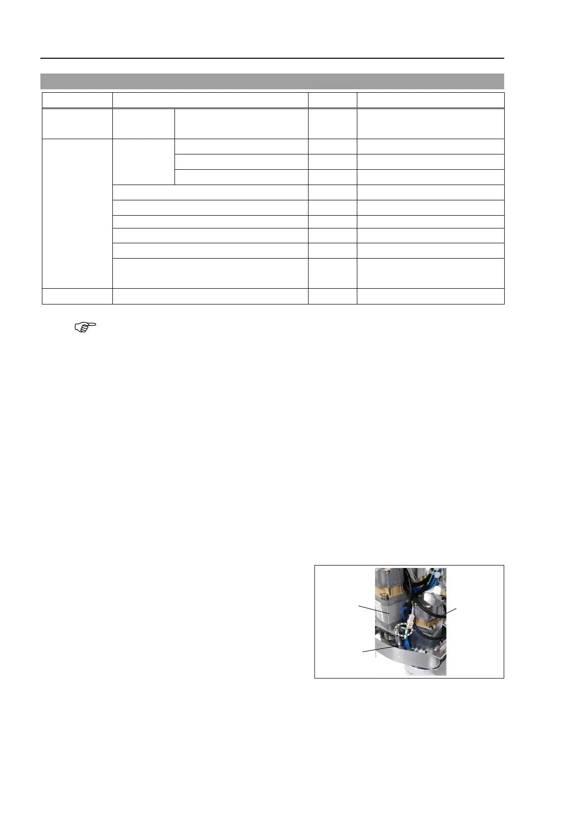
Cut off the wire tie binding the brake
cables.

 Loading...


