EasyManuals Logo

Epson T-B Series Maintenance Manual

Epson T-B Series
160 pages
To Next Page IconTo Next Page
To Previous Page IconTo Previous Page
Page #68 background imageLoading...
Page #68 background image
T3-B T6-B Maintenance 9. Joint #1
56 T-B series Maintenance Manual Rev.1
9.1 Replacing Joint #1 Motor
Name Quantity Note
Maintenance
parts
Motor
200W
1
T3-B: 2207934
300W
1
T6-B: 2207937
O-ring
Between reduction gear units
and Arm #1
1
T3-B: 1213266
T6-B: 1510528
Between reduction gear units
and flange
1
T3-B: 1868478
T6-B: 1868480
Between motor and flange 1
T3-B: 1709549
T6-B: 1520371
Elliptic cam positioning jig 1
T3-B: 1875189
T6-B: 1875190
Tools
Hexagonal
wrench
Width across flats: 2 mm 1
For M4 set screw
For M3 button bolt
Width across flats: 2.5 mm 1
For M3 screw
For M4 button bolt
Width across flats: 3 mm
1
For M4 screw
Width across flats: 3 mm
1
For M5 screw
Torque wrench
1
Cross-point screwdriver (No. 2)
1
For cross-recessed screw
Wiping cloth
1
For wiping grease
Grease
Grease
SFB No.1
-
Joint #1 motor
Removal
(1)
Turn OFF the Manipulator.
(2)
Remove the power unit cover.
Reference: 7.5 Power Unit Cover
(3)
Remove the connector plate.
Reference: 7.4 Connector Plate
(4)
Remove the following parts that connected to the
connector plate (inside).
Air tube
TP connector
(5)
T3
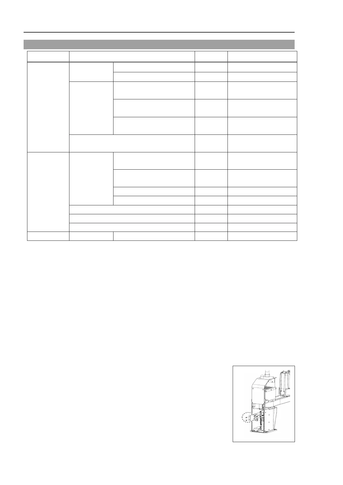
-B: Remove the base side cover.
Reference: 7.6 Base Side Cover
T6
-B: Remove the AMP board plate of joint #1.
2-M4×8 Sems

Table of Contents

Other manuals for Epson T-B Series

Questions and Answers:

Question and Answer IconNeed help?

Do you have a question about the Epson T-B Series and is the answer not in the manual?

Epson T-B Series Specifications

General IconGeneral
BrandEpson
ModelT-B Series
CategoryRobotics
LanguageEnglish

Related product manuals