T3-B T6-B Maintenance 10. Joint #2
80 T-B series Maintenance Manual Rev.1
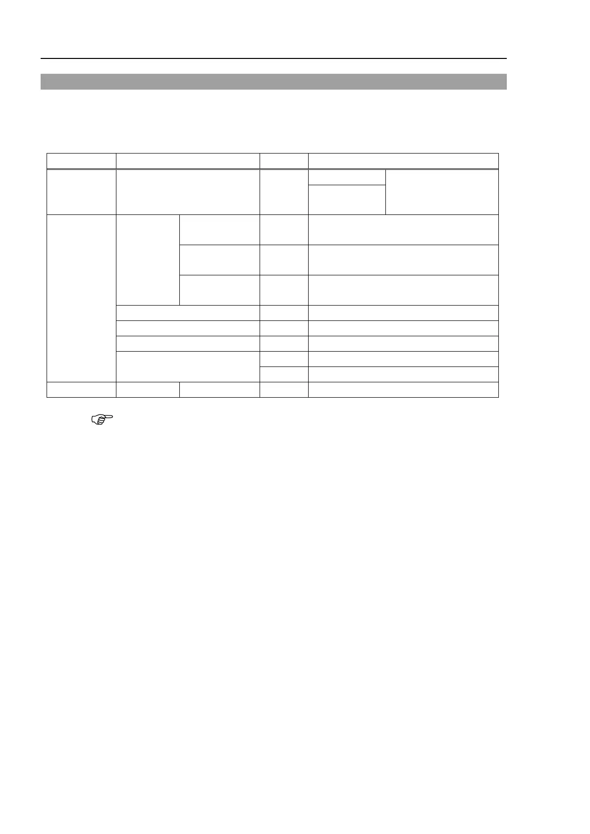
10.2 Replacing Joint #2 Reduction Gear Units
A reduction gear unit consists of the following three parts. When replacing the reduction
gear units, be sure to always replace the elliptic cam bearing, flex gear, and internal gear all
together as one set.
For details of the parts, refer to “19. Maintenance Parts List”.
Maintenance
part
Reduction gear units 1
units and elliptic cam
T6-B: 1829510
Tools
Hexagonal
wrench
Width across
1 For M4 set screw
Width across
1 For M3 screw
Width across
1 For M4 screw
Cross-point screwdriver (No. 2)
Wiping cloth
For wiping grease (Flange)
A brake is mounted on the Joint #3 motor to prevent the shaft from lowering down due to the
weight of the end effector while the power to the Manipulator is OFF or while the motor is
in OFF status (MOTOR OFF).
Refer to removal steps to move the shaft down to its lower limit before the replacement
procedure.
Remove Arm #2 and the reduction gear units from Arm #1.
Reference: 10.1 Replacing Joint #2 Motor “Removal procedure”
elliptic cam bearing from the Joint #2 motor.
Reference: 10.1 Replacing Joint #2 Motor “Removal procedure”

 Loading...


