T3-B T6-B Maintenance 10. Joint #2
T-B series Maintenance Manual Rev.1 79
Tighten screws to mount Arm #2 and the reduction gear units to Arm #1.
Loosely fasten all bolts in a
crisscross pattern so that the bolts will be fastened evenly.
T3-B: A: 8-M3×30+M3 small washer
B: 4-M3×15+M3 small washer
T6-B: A: 8-M3×32+8-M3 small washer
B: 4-M3×12+4-M3 small washer
Then, using a torque wrench, tighten each bolt securely in a cris
scross pattern at the
Tightening torque: 2.5 ± 0.15 N·m
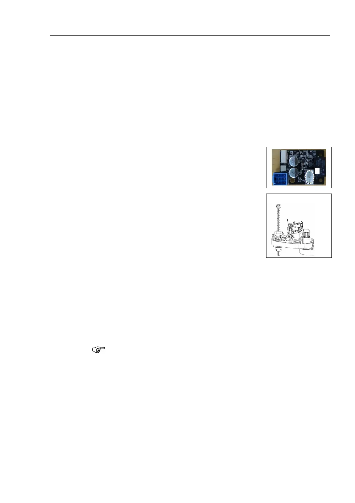
Mount the connector of the Joint #2 AMP board.
D: Motor cable connector
Mount the Joint # 2, 3, 4 AMP board unit to Arm #2.
2-M3×10 Sems
Joint #2, 3, 4
AMP Board Unit
Reference: 7.7 User Plate
Reference: 7.1 Arm Top Cover
Reference: T-B series Manual T3-B T6-B Manipulator 6.5 LED
When starting the Manipulator for the first time after replacing the motor unit, the
motor unit firmware is automatically updated. DO NOT turn OFF the power until the
Manipulator starts.
When you connect a motor unit connected to another axis, an error 5009 or 9709 will
occur. To clear the error, enter the following command in [Command Window] and
execute it.
Joint #1: > MUIDReset 1
Joint #2: > MUIDReset 2
Joint #3: > MUIDReset 3
Joint #4: > MUIDReset 4
Perform the calibration for the Joint #2.
Reference: 17. Calibration

 Loading...


