T3-B T6-B Maintenance 10. Joint #2
78 T-B series Maintenance Manual Rev.1
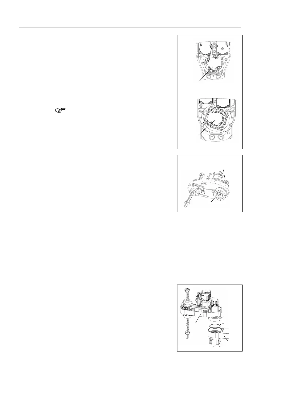
Secure temporarily the Joint #2 motor unit to Arm
#2.
T3-B: Motor flange mounting screws
3-M4×12+washer
T6-B: Motor mounting screws
4-M4×12+washer
motor, slowly move the Arm #2 by
Secure temporarily the screws. Perform an
alignment of the reduction gear units in the next
step.
Make sure that the screw head lightly touches the
flange base
Perform an alignment of the reduction gear units.
Grab the grease receiver by hand and rotate the
e
lliptic cam bearing three times clockwise.
Then, rotate three times counterclockwise.
Tighten the motor mounting screws which secured temporarily to secure the motor.
Loosely fasten all bolts in a crisscross pattern so that the bolts will be fastened evenly.
T3-B: Motor flange mounting screws 3-M4×10
T6-B: Motor mounting screws 4-M4×12
Then, using a torque wrench, tighten each bolt securely in a crisscross pattern at the
torque specified below.
Tightening torque: 4 ± 0.2 N·m
Mount Arm #2 and the reduction gear units to Arm
#1.
O-ring (between the reduction gear units
-ring to new one if there is swelling,

 Loading...


