T3-B T6-B Maintenance 10. Joint #2
74 T-B series Maintenance Manual Rev.1
10.1 Replacing Joint #2 Motor
Maintenance
part
Motor
O-ring
Between reduction gear
units and Arm #2
1
T3-B: 1868478
Elliptic cam positioning jig 1
T3-B: 1875189
Tools
Hexagonal
Cross-point
No.2 1 For cross-recessed screw
A brake is mounted on the Joint #3 motor to prevent the shaft from lowering down due to the
weight of the end effector while the power to the Manipulator is OFF or while the motor is
in OFF status (MOTOR OFF).
Refer to removal steps to move the shaft down to its lower limit before the replacement
procedure.
Motor
Press and hold the brake release switch to let the shaft down. Be sure to keep enough
space and prevent the end effe
ctor hitting any peripheral equipment.
The brake release switch affects only Joint #3. When the brake release switch is pressed,
the Joint #3 brake is released.
Be careful of the shaft falling while the brake release switch is being pressed because
the sh
aft may be lowered by the weight of the end effector.
Turn OFF the Manipulator.
Remove the Arm Top Cover.
Reference: 7.1 Arm Top Cover
Reference: 7.7 User Plate
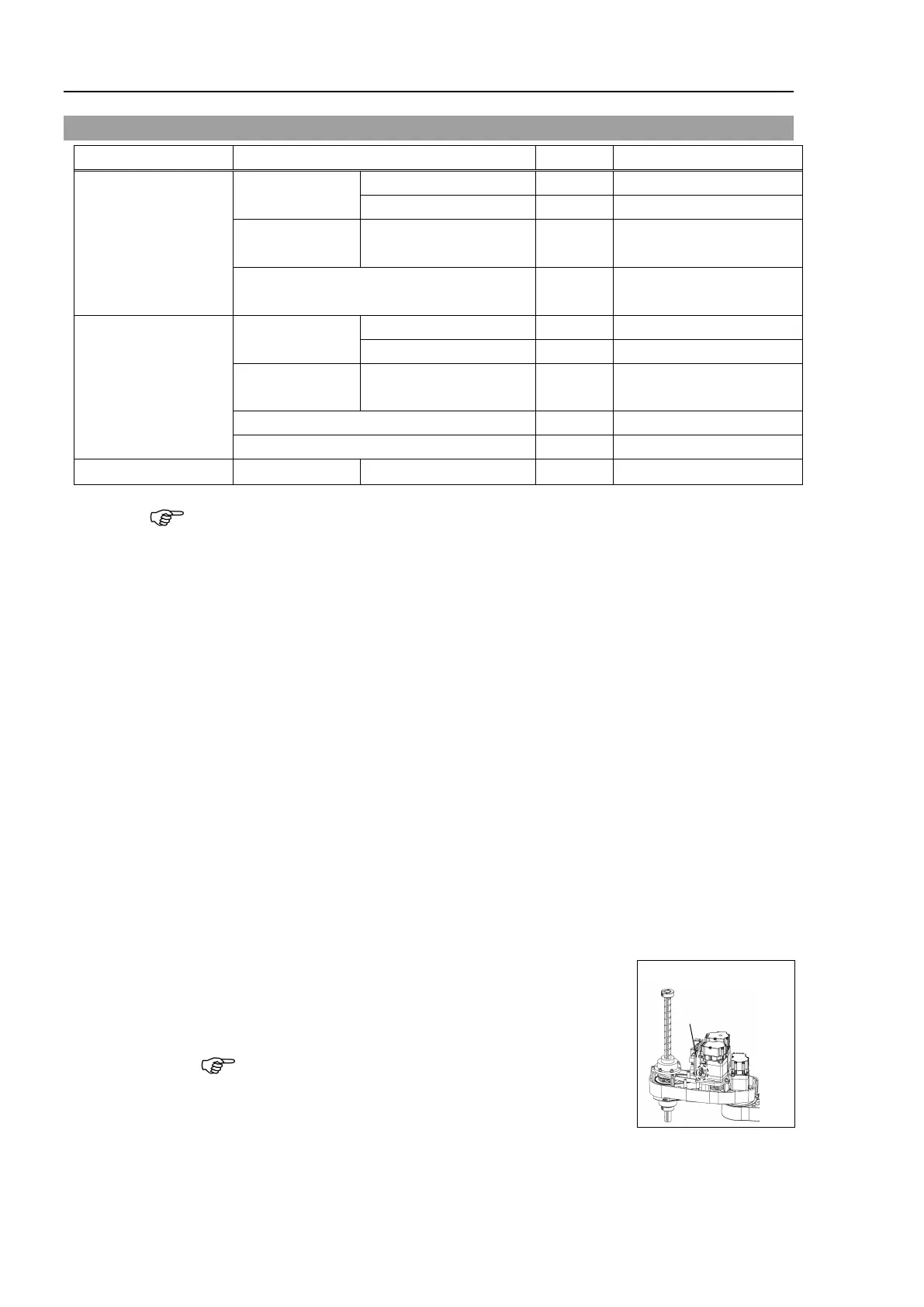
Loosen the mounting screws of the Joint #2,
3, 4 AMP board
unit, and remove the board unit from Arm #2.
2-M3×10 Sems
Do not remove the mounting screws and the connector.
Joint #2
, 3, 4
AMP Board Unit

 Loading...


