T3-B T6-B Maintenance 9. Joint #1
T-B series Maintenance Manual Rev.1 71
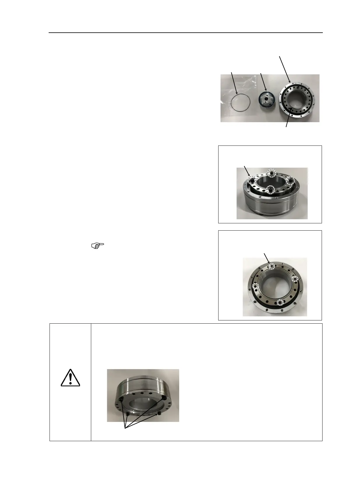
t
contains the
parts shown in the picture on the right
when it is unpacked.
The internal gear, tooth grooves of the flex
gear, and the
elliptic cam bearing are pre-
Wipe grease if it is attached to the
mounting surface of
the internal gear.
Internal gear + Flex gear
+ Cross roller bearing unit
Mounting surface of internal gear
-B : Unscrew the temporarily
securing screws (M3×4) of the
internal gear.
Temporarily securing screws
M3x4
-B : Do not unscrew the securing
screws (M3×4) of the internal
gear.
DO NOT
unscrew
the securing screws
M3
x4
CAUTION
■
Never adjust (loosen or tighten) the mounting bolts between the flex gear and
cross roller bearing unit.
If the bolts are adjusted, it requires centering of the parts by the reduction gear
unit
manufacturer.
DO NOT loosen these four bolts

 Loading...


