12 13
TM-U220A
Specification
(For Argentina Fiscal)
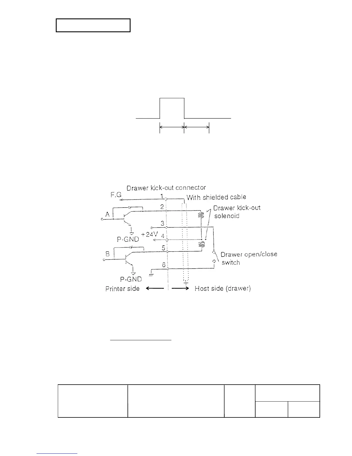
3) Drawer kick-out drive signal
Output signal: Output voltage: Approximately 24 V
Output current: 1 A or less
CAUTION: To avoid an overcurrent, the resistance of the drawer kick-out solenoid must be
24
Ω or more.
Output waveform: Outputs the waveforms in Figure 2.3.3 to the points A and B in Figure 2.3.4.
(
ESC p or DLE DC4 specifies ON time and OFF time.)
t1
×
2 ms
t2
×
2 ms
(by
ESC p
)
t
×
100 ms
t
×
100 ms
(by
DLE DC4
)
Figure 2.3.3 Drawer Kick-out Drive Signal Output Waveform
4) Drawer open/close signal
Input signal level (connector pin 3): “L” = 0 V, “H” = 2 to 5 V
Figure 2.3.4 Drawer Circuitry
NOTES: 1. Use a shielded cable for the drawer connector cable.
2. Two driver transistors cannot be energized simultaneously.
3. The drawer drive duty must be as shown below:
On time
(ON time + OFF time)
≤ 0.2
4. Be sure to use the printer power supply (connector pin 4) for the drawer power source.
5. The resistance of the drawer kick-out solenoid must not be less than the specified.
Otherwise, an overcurrent could damage the solenoid.